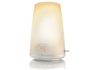
I know everyone has likely moved on here but for anyone finding this issue today on the Phillips HF3470..
The buttons are a "right angle pcb mount tactile momentary micro switch" or something like that. 5mm spacing on the switch pins with PCB mounting pins behind at 7mm spacing. I found a 10 pack on ebay. Pacer PTA-116AJ. Made for Motorola. Hopefully these will fit and work better.
You can open of the clock, it's a real PITA to get all the clips to release to separate the bottom from the clock and get at the circuit boards. But it's not impossible esp if you don't care if the outer case gets marred up some.
On my wife's light, the light up/down buttons on the side were not working properly. There are more switches on the main circuit board but they are the same type.
The vertical buttons on the side are on one circuit board as part of a subassembly. The assembly has a wire/molex connector that goes and plugs into the main board with the clock display. Unplug that and this can be pretty easily taken apart to remove the circuit board. Theres some really small c clips on the pivot for the lever. Good luck not losing one when you pop it off. But can probably be substituted with some super glue or something. Rest of it comes apart straight forward after you peel a piece of plastic film off the side to gain access to two screws.
So.. here's the crux of the issue with the button controls on this unit. The micro switches don't each have their own circuit. They are all wired up to a main "loop" with different value resistors between each switch termination to the loop. So then the output from the board is the ground and "data". Each button completes the circuit but with a distinctly different resistance, and therefore voltage drop/or current at the "data" pin. A microcontroller interprets this value into the corresponding function. Sounds like a lovely, spacing saving, material saving design right? Yes, it's great when everything is working properly. The problem is when the switches start to wear out, they start adding some of their own resistance to the the circuit. This renders the function of the button inoperable, or can trigger a completely different function. If you press the switch just right before it's completely shot, the function works, but press it wrong and chaos! hah
Replacing these switches doesn't seem like too bad a proposition if you are an experienced in electronics soldering. The board doesn't have a ton going on. Just be careful not to damage any pads or desolder any of the resistors. If those one comes loose the whole thing is toast unless you can get it replaced. They are VERY tiny. I have yet to try and fix this lamp, the switches are on order. I was thinking of desoldering using a heat gun but I think a wick is a better way to go here with the resistors at risk.
I'll update this after my attempt. If anyone needs pictures let me know and I'll upload some.
Был ли этот ответ полезен?
Проголосовали
Отменить
Оценка
0
Отмена
Scroll through this thread to find the appropriate place for this comment. Then, click "Attach comment to this post" to move it.


 2
2  1
1
3 Комментариев
из Victor
I'm also having this issue. None of the buttons work at all. Anyone found a solution internally?
из Noah
Had same problem.
After going through each of the PCBs it tured out that one of the button fas not working and disturbed the function of the others.
I just removed VOL DOWN and everything started to work (except vol down). Replaced it with a cheap one from ebay and now it's just as new!
из Jonas Månsson