Перейти к основному содержанию

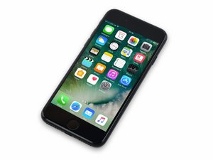
Выпущен 16 сентября 2016 года. Модель 1660, 1778. Стандарты связи GSM или CDMA. Память 32, 128 или 256 ГБ. Цвета: розовое золото, золотой, серебристый, черный и глянцевый черный.

2264вопросов Показать все

Distorted display, colored lines in LCD even after replacement.

Got a tricky one here.

Customer brought in an iPhone 7 that was dropped a few months back which caused the glass to break around the home button. The customer says that the phone has been working fine up until yesterday morning when he woke up and the display was distorted with multicolored lines over the display. This screen distortion would flash in and out. Meaning, the distortion would appear over the screen for several seconds and then return to a perfectly normal display and then back to the distortion and repeat ad nauseum.

The distortion begins as soon as you turn the phone on. You see the Apple logo and the display is fine and a few moments later, half of the screen will distort for a few moments and then return to the normal Apple logo boot up screen where it continues to randomly distort throughout the use of the phone, always returning back to a normal display for a seemingly random amount of time before it distorts again.

He brought it into my shop and seeing the damage to the display around the home button and the distorted display, I figured this was another typical screen replacement job. Wrong. So far, I have:

  • Replaced the LCD. Twice. The distortion continues on both new displays.
  • Tried connecting the displays without the front camera flex cable - no effect.
  • DFU mode restore on iOS 11.3 - no effect.
  • Removed logic board and examined the components under a microscope to see if I could see any obvious damage like knocked off components from when he dropped it, etc. - Saw none.

Kind of at a loss of where to go next. I'm somewhat experienced with troubleshooting and repairing board-level components usually with things like back-light coils, diodes, and even a touch IC once or twice. Any advice on where to go from here?

Attaching photos and videos.

Block Image

Block Image

[UPDATE: 4/14/18:] - Additional Notes. -

  • I have noticed that the distortion does not take place while anywhere in the Settings app. I can freely move anywhere within the Settings app for as long as I please and this distortion will not appear. As soon as I leave the Settings app however, it resumes almost immediately
  • Measured FL3903, FL3901, and FL3902 in diode mode and all appeared to be in good working order.
  • Measured each pin of J4502 in diode mode and found several pins to read 0L including Pin 5, Pin 6 and others. I believe this may point to a Chestnut IC related problem, but I am not sure. I have advised the customer that replacing his phone might be the quickest, cheapest option since a refurb. iPhone 7 goes for $369. Posting what I found in case it helps someone else track down the fix.
Отвечено! Посмотреть ответ У меня та же проблема

Это хороший вопрос?

Оценка 0
Добавить комментарий

1 ответ

Выбранное решение

Hmmm, I haven't seen that problem specifically but I would suspect it is much more than your typical Chestnut problem. This looks like it could be corruption in the actual data from the CPU or perhaps a synchronization issue. Take a look at the common mode chokes that filter out the various 90_MIPI_AP_TO_LCM data lines. Also do diode measurements on J4502 against a known-good connector or pre-established readout in ZXW.

Был ли этот ответ полезен?

Оценка 3

4 Комментариев:

Thanks for the reply. L3901 reads 3.0 Ohms, L3902 reads 2.8 Ohms, and L3903 reads 2.7 Ohms. Could you elaborate a bit more about the diode measurements on J4502? Thanks again.

из

You have to measure both sides of the chokes (i.e. pins 1 & 2, look at the schematic). All the chokes should read the same thing...they should be balanced. It's easier to measure these in diode mode.

As for the connector, measure each pin in diode mode and compare to known-good connector or published measurements.

If you found this answer helpful, please select "Was this answer helpful? - YES" and/or if this answer solved your problem, please “Choose as Solution”. This allows people in the future to understand which answers helped solve the problem and adds value to the site. - Thanks

из

Thanks again for the clarification. Still quite new to this level of repair. So after taking new measurements in diode mode, each choke read the same as the other.

I don't have a known good J4502 on hand at the moment, but began taking readings of each pin and recording my findings on each one and have found several pins that read 0L - starting with Pin 5. Is this a sign of Chestnut failure?

из

OL just simply means nothing is connected that has a path or partial path to ground. When you measure in diode mode, you are applying a 3V voltage to the circuit. That voltage is trying to complete a full circuit, from the red probe to the black probe. If a circuit is directly shorted to ground, you will read 0V. If the circuit is, for example, just a capacitor, it will read 3V or OL because it is an open circuit (OL) with no path to ground.

If the circuit includes transistors or diodes, like those within an IC, then you will measure a partial voltage, like 0.530V which represents the voltage drop within the circuit. Why that number is what it is is very complicated but by comparing to a known-good circuit, you can see if those hidden internal conditions are the same.

All that to say that when you see 0V or OL and you don't have known-good measurements to compare them to, you need to look at the circuit and see if it makes sense.

из

Добавить комментарий

Добавьте свой ответ

TechWizard будет вечно благодарен.
Просмотр статистики:

За последние 24часов: 1

За последние 7 дней: 2

За последние 30 дней: 20

За всё время: 3,169