Эта версия возможно содержит некорректные исправления. Переключить на последнюю проверенную версию.
Выберете то, что вам нужно
-
Этот шаг не переведен. Помогите перевести
-
With the opening facing you, flip the laptop over and remove the following screws from the back panel:
-
Six 4mm Phillips screws using a Phillips #0 screwdriver.
-
One 12mm Phillips screw in the center using a Phillips #0 screwdriver.
-
-
Этот шаг не переведен. Помогите перевести
-
Using a plastic spudger, remove the two rubber stoppers closest to the hinge to reveal the screws underneath.
-
-
Этот шаг не переведен. Помогите перевести
-
Remove the following screws:
-
Two 4mm Phillips screws using a Phillips #0 screwdriver.
-
-
Этот шаг не переведен. Помогите перевести
-
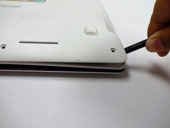
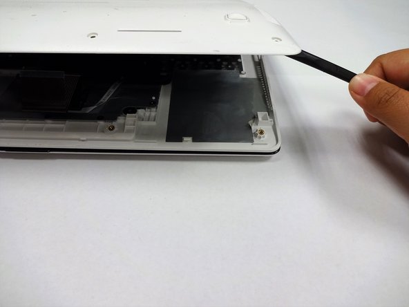
Using a plastic spudger (and a fair amount of force), pry the back panel up from the keyboard to separate.
-
-
Этот шаг не переведен. Помогите перевести
-
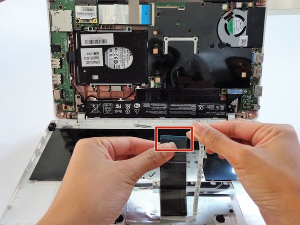
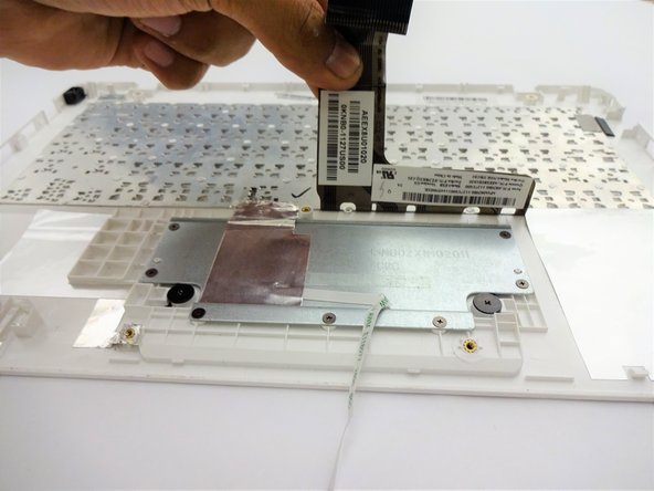
To disconnect the keyboard connectors from keyboard and back panel, gently pull wide keyboard connector out.
-
Gently pull the narrow connector away from the keyboard.
-
-
Этот шаг не переведен. Помогите перевести
-
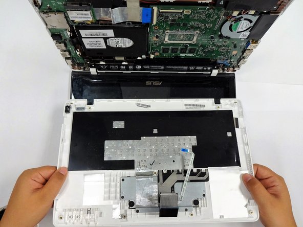
Now that the keyboard connectors are unplugged, pull the keyboard off and away from the back panel hinges.
-
-
Этот шаг не переведен. Помогите перевести
-
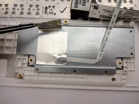
Remove the following screws:
-
Eight 3 mm screws using Phillips screwdriver.
-
-
Этот шаг не переведен. Помогите перевести
-
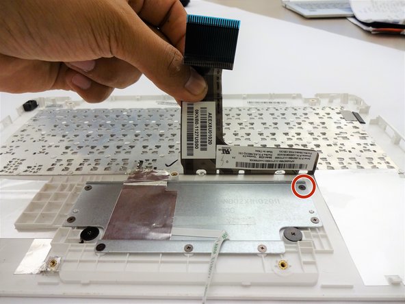
Remove the following screws:
-
Two 2 mm screws using a Phillips #00 screwdriver.
-
-
-
Этот шаг не переведен. Помогите перевести
-
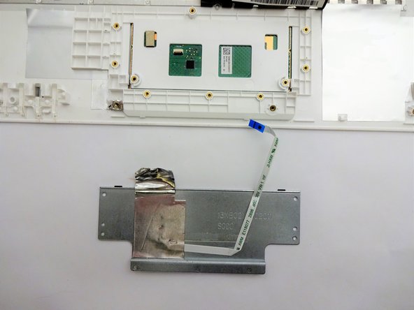
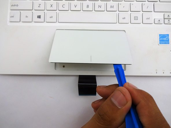
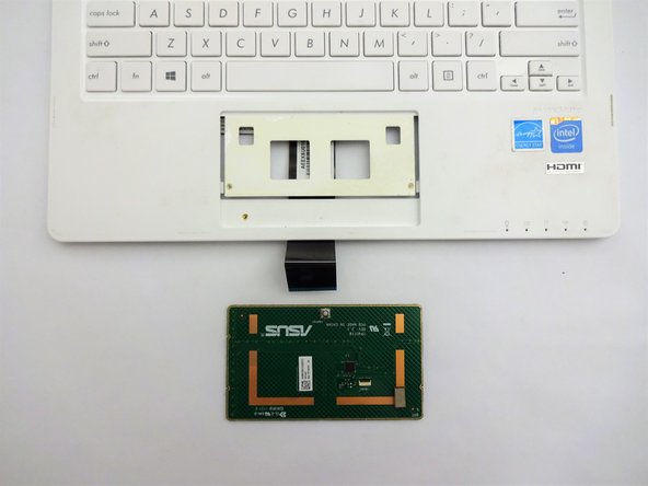
Flip the keyboard over.
-
Using a plastic spudger, pry the track pad off the plastic piece underneath.
-
-
Этот шаг не переведен. Помогите перевести
-
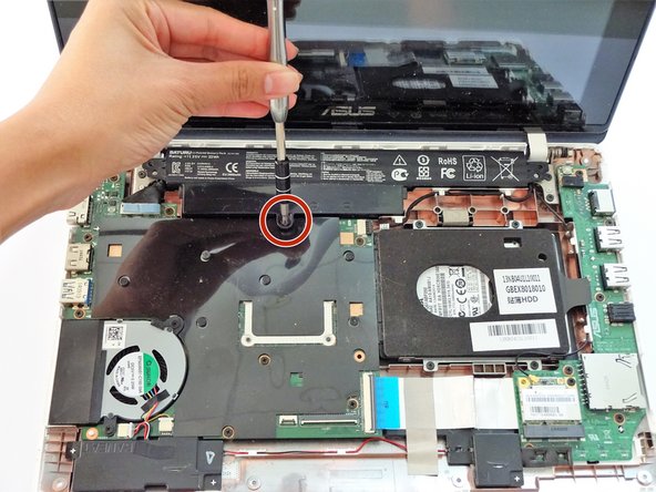
Flip the computer over so that the side with the motherboard (large green piece) is laying face-up.
-
Remove the following screws from the middle and far ends of the battery:
-
Three 4mm Phillips screws using a Phillips #0 screwdriver.
-
-
Этот шаг не переведен. Помогите перевести
-
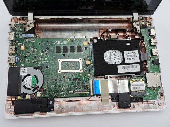
Gripping the wider left section, lift the battery up and away from computer.
-
-
Этот шаг не переведен. Помогите перевести
-
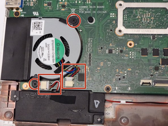
Locate the fan, two screws and two color coded wires in the bottom left corner of the computer.
-
-
Этот шаг не переведен. Помогите перевести
-
Remove the following screws from the fan:
-
Two 4mm screws using a Phillips #0 screwdriver.
-
-
Этот шаг не переведен. Помогите перевести
-
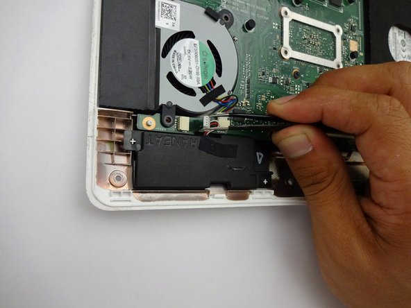
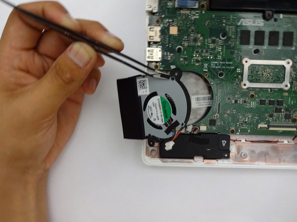
After removing both the screws and color coded wires, lift fan out of place.
-
-
Этот шаг не переведен. Помогите перевести
-
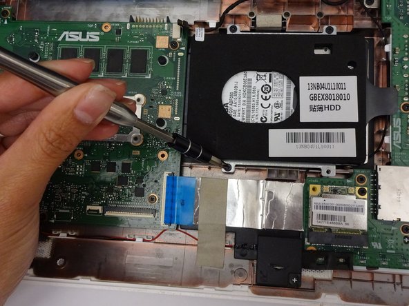
Remove the following screws:
-
Four 4mm Phillips screws using a Phillips #0 screwdriver.
-
-
Этот шаг не переведен. Помогите перевести
-
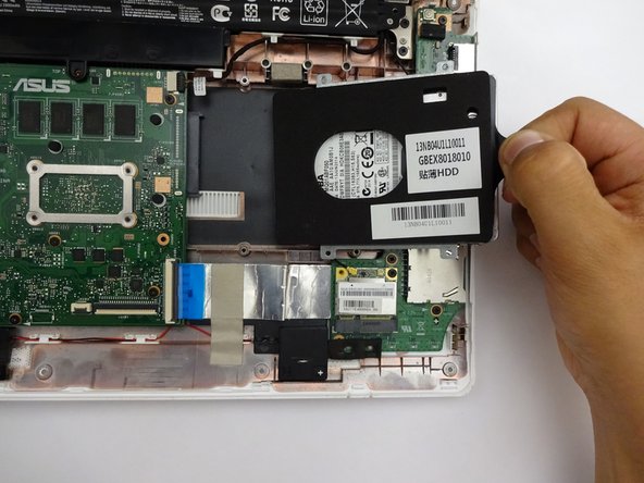
Remove by sliding hard driving right and away from the computer using the tag on the right side.
-
-
Этот шаг не переведен. Помогите перевести
-
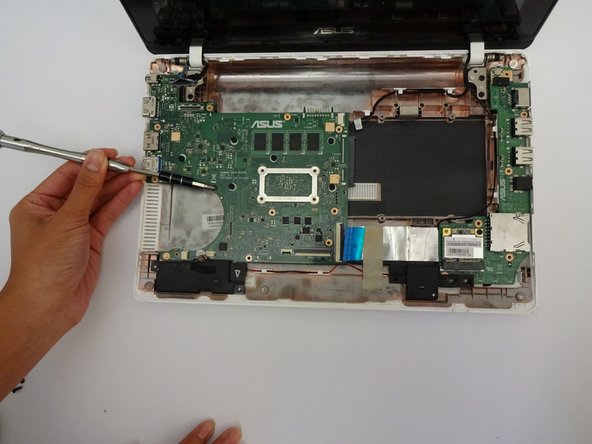
Locate and remove the following screws on the motherboard:
-
Eighteen 4mm Phillips screws using a Phillips #0 screw driver.
-
-
Этот шаг не переведен. Помогите перевести
-
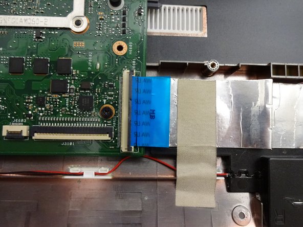
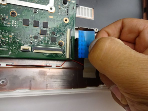
Use the blue ribbon to vertically pull the connector away from the mother board.
-
-
Этот шаг не переведен. Помогите перевести
-
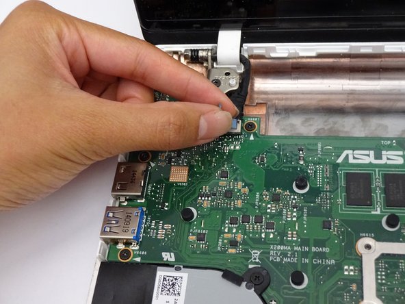
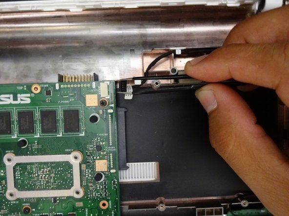
Lift the latch upwards to release the computer ribbon connector.
-
-
Этот шаг не переведен. Помогите перевести
-
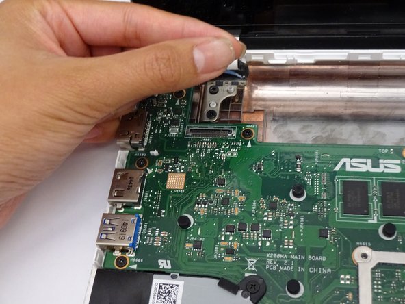
Horizontally pull the computer ribbon cable away from latch.
-
-
Этот шаг не переведен. Помогите перевести
-
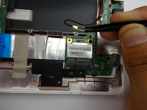
Vertically pull the cable from the head away from the placement.
-
-
Этот шаг не переведен. Помогите перевести
-
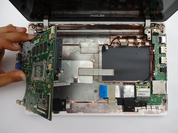
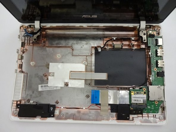
Once all screws and connectors are removed, gently lift the motherboard from computer.
-
-
Этот шаг не переведен. Помогите перевести
-
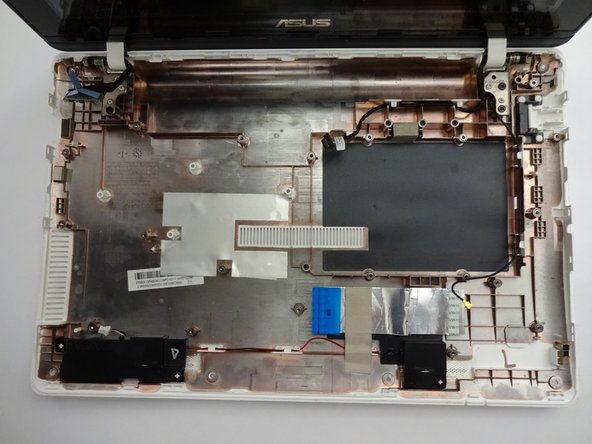
Remove the final piece of the motherboard on the right-hand side of the keyboard shell.
-


Команда

CSU Fullerton, Team S2-G5, Bruce Fall 2018 Участник CSU Fullerton, Team S2-G5, Bruce Fall 2018
CSUF-BRUCE-F18S2G5
4 членов
Автор 7 руководств