Перейти к основному содержанию

ASUS Q324UA-BHI7T17 Power & Volume Button PCB Board Replacement

Выберете то, что вам нужно

  1. ASUS Q324UA-BHI7T17 Power & Volume Button PCB Board Replacement, Battery: шаг 1, изображение 1 из 1
    • Remove all 10 Phillips screws on the backplate.

    • All 10 screws are 0.55 inches and 20 mm in diameter.

  2. ASUS Q324UA-BHI7T17 Power & Volume Button PCB Board Replacement: шаг 2, изображение 1 из 2 ASUS Q324UA-BHI7T17 Power & Volume Button PCB Board Replacement: шаг 2, изображение 2 из 2
    • Carefully remove the backplate using the plastic opening tool.

  3. ASUS Q324UA-BHI7T17 Power & Volume Button PCB Board Replacement: шаг 3, изображение 1 из 1
    • Locate the battery near the bottom.

  4. ASUS Q324UA-BHI7T17 Power & Volume Button PCB Board Replacement: шаг 4, изображение 1 из 1
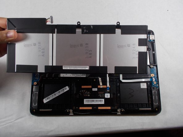
    • Next, lift up the battery connector from the laptop in the upper left side of the battery, using tweezers or spudger.

    • Make sure to complete this step with caution, because if the battery is not unplugged, the motherboard may shock you.

  5. ASUS Q324UA-BHI7T17 Power & Volume Button PCB Board Replacement: шаг 5, изображение 1 из 2 ASUS Q324UA-BHI7T17 Power & Volume Button PCB Board Replacement: шаг 5, изображение 2 из 2
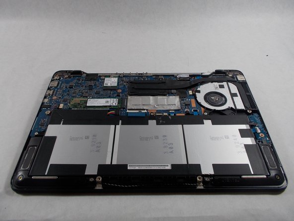
    • Remove the six screws holding in the battery with a Phillips #0 screwdriver.

    • Once battery is lifted out and removed, proper dispose of the old battery.

    • Each screw is 0.5 cm in length and 0.5 cm in diameter.

  6. ASUS Q324UA-BHI7T17 Power & Volume Button PCB Board Replacement, Power & Volume Button PCB Board: шаг 6, изображение 1 из 1
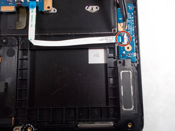
    • Remove the screw holding the Power chip in place and remove it using a Phillips head #0 screw driver.

    • Screw length is 0.5 cm in length and 0.5 cm in diameter

  7. ASUS Q324UA-BHI7T17 Power & Volume Button PCB Board Replacement: шаг 7, изображение 1 из 3 ASUS Q324UA-BHI7T17 Power & Volume Button PCB Board Replacement: шаг 7, изображение 2 из 3 ASUS Q324UA-BHI7T17 Power & Volume Button PCB Board Replacement: шаг 7, изображение 3 из 3
    • Locate the ribbon connector connecting the power chip to the mother board.

    • Simply lift up the black component and the ribbon connector should be released, then the power chip should pop out easily.

    • Discard of the old power chip properly.

Заключение

To reassemble your device, follow these instructions in reverse order.

Scott Santiago

Участник с: 10/17/17

534 Репутация

Автор 5 руководств

Команда

UMass Dartmouth, Team S1-G1, Simcock Fall 2017 Участник UMass Dartmouth, Team S1-G1, Simcock Fall 2017

UMASSD-SIMCOCK-F17S1G1

3 членов

Автор 5 руководств

0 Комментариев

Добавить комментарий

Просмотр статистики:

За последние 24часов: 0

За последние 7 дней: 0

За последние 30 дней: 1

За всё время: 639