Перейти к основному содержанию

Asus ROG G751JL-BB17T29 Display Replacement

Выберете то, что вам нужно

  1. Asus ROG G751JL-BB17T29 Display Replacement, Remove the RAM access door: шаг 1, изображение 1 из 2 Asus ROG G751JL-BB17T29 Display Replacement, Remove the RAM access door: шаг 1, изображение 2 из 2
    • Use an opening tool to pry up the small rubber cover on the upper right corner of the RAM access door.

  2. Asus ROG G751JL-BB17T29 Display Replacement: шаг 2, изображение 1 из 1
    • Remove the 5.3 mm Phillips #00 screw securing the RAM access door.

    • This screw is held in the hole in the door with a washer and will not come out of the hole, even after you unscrew it.

  3. Asus ROG G751JL-BB17T29 Display Replacement: шаг 3, изображение 1 из 2 Asus ROG G751JL-BB17T29 Display Replacement: шаг 3, изображение 2 из 2
    • Insert the point of an opening pick in the seam near the top right corner of the RAM access door and gently pry the door up slightly.

    • The door is held in place by small clips around its edges. Pry until you feel the nearest clips release.

  4. Asus ROG G751JL-BB17T29 Display Replacement: шаг 4, изображение 1 из 3 Asus ROG G751JL-BB17T29 Display Replacement: шаг 4, изображение 2 из 3 Asus ROG G751JL-BB17T29 Display Replacement: шаг 4, изображение 3 из 3
    • Insert the wide edge of an opening pick into a new part of the seam between the door and the computer.

    • Pry the door up to release the clips closest to the pick.

    • Continue to slide the pick along the seam all the way around the door, prying as you go, until all the clips holding the door down have been released.

  5. Asus ROG G751JL-BB17T29 Display Replacement: шаг 5, изображение 1 из 1
    • Remove the RAM access door.

  6. Asus ROG G751JL-BB17T29 Display Replacement, Remove the optical drive: шаг 6, изображение 1 из 1
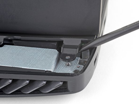
    • Remove the 5.2 mm Phillips #00 screw securing the optical drive.

  7. Asus ROG G751JL-BB17T29 Display Replacement: шаг 7, изображение 1 из 3 Asus ROG G751JL-BB17T29 Display Replacement: шаг 7, изображение 2 из 3 Asus ROG G751JL-BB17T29 Display Replacement: шаг 7, изображение 3 из 3
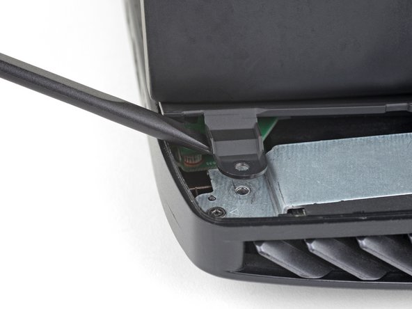
    • Insert an opening tool into the gap between the optical drive and the laptop.

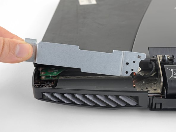
    • Pry the optical drive straight out of the laptop.

    • Remove the optical drive.

  8. Asus ROG G751JL-BB17T29 Display Replacement, Remove the case screws: шаг 8, изображение 1 из 1
    • Use the point of a spudger to pry out eleven rubber plugs covering the screws on the bottom of the laptop.

    • Some plugs have a hole or notch into which you can insert the point of a spudger to more easily pry out the plugs.

  9. Asus ROG G751JL-BB17T29 Display Replacement: шаг 9, изображение 1 из 2 Asus ROG G751JL-BB17T29 Display Replacement: шаг 9, изображение 2 из 2
    • Remove 18 Phillips #00 screws of the following lengths:

    • Eight 8.8 mm screws

    • Seven 5.2 mm screws

    • Three screws

  10. Asus ROG G751JL-BB17T29 Display Replacement, Remove the battery cover: шаг 10, изображение 1 из 3 Asus ROG G751JL-BB17T29 Display Replacement, Remove the battery cover: шаг 10, изображение 2 из 3 Asus ROG G751JL-BB17T29 Display Replacement, Remove the battery cover: шаг 10, изображение 3 из 3
    • Flip the laptop right-side up.

    • Use an opening pick to pry the left and right edges of the battery cover away from the laptop enough that you can grip the cover with your fingers.

  11. Asus ROG G751JL-BB17T29 Display Replacement: шаг 11, изображение 1 из 2 Asus ROG G751JL-BB17T29 Display Replacement: шаг 11, изображение 2 из 2
    • Lift the battery cover straight up from the laptop.

    • Do not try to completely remove the cover yet, it is still tethered by a speaker cable.

  12. Asus ROG G751JL-BB17T29 Display Replacement, Disconnect the speaker cable: шаг 12, изображение 1 из 2 Asus ROG G751JL-BB17T29 Display Replacement, Disconnect the speaker cable: шаг 12, изображение 2 из 2
    • Pull the speaker connectors straight away from each other to disconnect the speaker cable.

    • Make sure the speaker cable is out of the way before you reinstall the battery cover.

  13. Asus ROG G751JL-BB17T29 Display Replacement, Remove the upper case assembly: шаг 13, изображение 1 из 3 Asus ROG G751JL-BB17T29 Display Replacement, Remove the upper case assembly: шаг 13, изображение 2 из 3 Asus ROG G751JL-BB17T29 Display Replacement, Remove the upper case assembly: шаг 13, изображение 3 из 3
    • Open the laptop's display to a 90° angle.

    • Use a spudger to pry against one of the screw tabs on the back of the upper case assembly.

    • Make sure to pry as close as possible to the base of the tab to avoid damaging the tab.

    • Repeat this procedure with the other tab.

    • The upper case assembly is held in place by small clips around its edges. In this step, pry each tab up until you feel the nearest clips release.

  14. Asus ROG G751JL-BB17T29 Display Replacement: шаг 14, изображение 1 из 2 Asus ROG G751JL-BB17T29 Display Replacement: шаг 14, изображение 2 из 2
    • Insert the flat end of a spudger in the gap between the laptop and the upper case assembly, near the display.

    • If there's not a big enough gap, repeat the previous step until you have space to insert the spudger.

  15. Asus ROG G751JL-BB17T29 Display Replacement: шаг 15, изображение 1 из 3 Asus ROG G751JL-BB17T29 Display Replacement: шаг 15, изображение 2 из 3 Asus ROG G751JL-BB17T29 Display Replacement: шаг 15, изображение 3 из 3
    • Slide the spudger along each edge of the upper case assembly, prying and releasing clips as you go.

  16. Asus ROG G751JL-BB17T29 Display Replacement: шаг 16, изображение 1 из 3 Asus ROG G751JL-BB17T29 Display Replacement: шаг 16, изображение 2 из 3 Asus ROG G751JL-BB17T29 Display Replacement: шаг 16, изображение 3 из 3
    • When all the clips securing the upper case assembly have been released, lift the assembly slightly and slide it down, away from the display, about an inch.

    • Do not attempt to remove the assembly yet. It is still attached to the laptop by four cables.

  17. Asus ROG G751JL-BB17T29 Display Replacement: шаг 17, изображение 1 из 3 Asus ROG G751JL-BB17T29 Display Replacement: шаг 17, изображение 2 из 3 Asus ROG G751JL-BB17T29 Display Replacement: шаг 17, изображение 3 из 3
    • Use the tip of a spudger to flip up the small locking flap of the keyboard backlight cable ZIF connector.

    • Be sure to pry up on the hinged flap, not the connector socket.

    • Gently pull the cable out of its socket.

  18. Asus ROG G751JL-BB17T29 Display Replacement: шаг 18, изображение 1 из 3 Asus ROG G751JL-BB17T29 Display Replacement: шаг 18, изображение 2 из 3 Asus ROG G751JL-BB17T29 Display Replacement: шаг 18, изображение 3 из 3
    • Repeat the previous step for the keyboard, trackpad buttons, and trackpad cables held in place by ZIF connectors.

  19. Asus ROG G751JL-BB17T29 Display Replacement: шаг 19, изображение 1 из 1
    • Remove the upper case assembly.

  20. Asus ROG G751JL-BB17T29 Display Replacement, Disconnect the battery: шаг 20, изображение 1 из 2 Asus ROG G751JL-BB17T29 Display Replacement, Disconnect the battery: шаг 20, изображение 2 из 2
    • Pull the battery cable away from the connector in the same direction as the individual wires are running to disconnect the battery.

    • Pull evenly on the full width of the cable so that no individual wires are overly strained.

  21. Asus ROG G751JL-BB17T29 Display Replacement, Remove the display: шаг 21, изображение 1 из 2 Asus ROG G751JL-BB17T29 Display Replacement, Remove the display: шаг 21, изображение 2 из 2
    • Grab the black tape attached to the display cable and pull straight up to disconnect the display cable.

  22. Asus ROG G751JL-BB17T29 Display Replacement: шаг 22, изображение 1 из 3 Asus ROG G751JL-BB17T29 Display Replacement: шаг 22, изображение 2 из 3 Asus ROG G751JL-BB17T29 Display Replacement: шаг 22, изображение 3 из 3
    • Slide the point of a spudger under the black antenna cable until it's snug against the connector, and pry straight up from the board to disconnect the antenna cable.

    • Follow the same procedure to disconnect the white antenna cable.

    • To reinstall these antenna cables, hold the connectors in place and gently press them straight down. The connectors “snap” into their sockets much like the metal snaps on a jacket.

    • Make sure to plug each cable into the correct socket during reassembly. The white cable should plug into the upper socket, while the black cable plugs into the lower.

  23. Asus ROG G751JL-BB17T29 Display Replacement: шаг 23, изображение 1 из 3 Asus ROG G751JL-BB17T29 Display Replacement: шаг 23, изображение 2 из 3 Asus ROG G751JL-BB17T29 Display Replacement: шаг 23, изображение 3 из 3
    • Remove the nine Phillips screws securing the display:

    • Four 6.8 mm Phillips #0 screws

    • Three 8.6 mm Phillips #00 screws

    • Two 5.2 mm Phillips #00 screws

  24. Asus ROG G751JL-BB17T29 Display Replacement: шаг 24, изображение 1 из 2 Asus ROG G751JL-BB17T29 Display Replacement: шаг 24, изображение 2 из 2
    • Lift up and remove the two metal display brackets.

  25. Asus ROG G751JL-BB17T29 Display Replacement: шаг 25, изображение 1 из 1
    • Lift the monitor straight up and remove it.

Заключение

To reassemble your device, follow the above steps in reverse order.

Take your e-waste to an R2 or e-Stewards certified recycler.

Repair didn’t go as planned? Check out our Answers community for troubleshooting help.

4 участников успешно повторили данное руководство.

Kristofer Cesaroni

Участник с: 10/06/16

983 Репутация

Автор 8 руководств

Команда

USF Tampa, Team 2-1, Sullivan Fall 2016 Участник USF Tampa, Team 2-1, Sullivan Fall 2016

USFT-SULLIVAN-F16S2G1

4 членов

Автор 20 руководств

3 Комментариев

You have left out TWO very important steps.  A) tools needed: a - fine tweezer and b - magnifier glass [ and a lot of patience }.

With the open computer facing you. On the left side two gold electrode wires connect to the motherboard, note the wire placement of the two.

On the right side there is a ribbon connector on the right side. NOTE, when the monitor is lifted out, these will COME OFF. If you are a notice, you will be lost. My guess the new monitor will have these connector.  To rebuild: place the set screws for the monitor and then the left and right rear brackets. Go back to front view and insert the back ribbon connector to the motherboard on the right backside. Take a break. Use the magnifier glass and tweezer and attempt to align the SMALL ELECTRODE heads. When aligned they can be pressed on, a light snap will be heard. Please be carefull. This step took me 1 hour. After these steps, continue re-assembly.

Regard,

D C

Douglas Crews - Ответить

Would the display connector be the same for the touchscreen model? Or is there an additional cable/different connector?

Daniel Sierra - Ответить

Добавить комментарий

Просмотр статистики:

За последние 24часов: 3

За последние 7 дней: 11

За последние 30 дней: 47

За всё время: 8,750