Введение
This guide will teach you how to replace the Asus Zen AiO heat sink. No prior knowledge is required.
Выберете то, что вам нужно
-
-
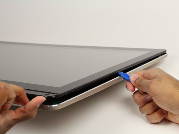
Use the plastic opening tool to pry off the black plastic strip at the bottom of the screen by wiggling the tool between the strip and the screen.
-
Run the opening tool slowly along the base of the screen, peeling the black strip back, until the opposite end of the screen is reached.
-
-
-
Use a Phillips #1 screwdriver to remove the seven (7) 4.8 mm screws from the base of the screen.
-
-
-
Place the computer on its back, facing up.
-
Wedge the plastic opening tool in between the screen and the bezel of the aluminum computer casing.
-
Move the tool along the entire edge of the screen with an up-and-down prying motion to loosen the screen from the casing. Do not lift the entire screen away from the computer yet.
-
-
-
Lift the screen from the bottom edge by about 6 inches. Prop it open with one hand.
-
Look inside the computer and locate five (5) cables that connect the embedded components of the screen (camera, microphone, etc.) to the rest of the computer.
-
-
-
Remove the two (2) cables that are connected to the computer by white, rectangular terminal blocks by pulling straight out on the plug.
-
-
-
Use a finger to lift the plastic locking flaps that hold the remaining three (3) ribbon cables in place.
-
Remove the cables from their terminals by slipping them away from their connectors.
-
-
-
-
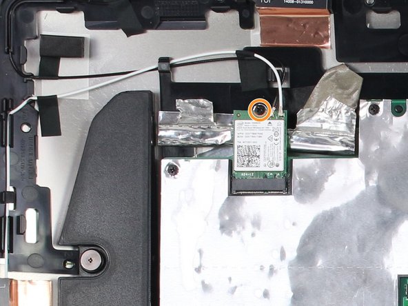
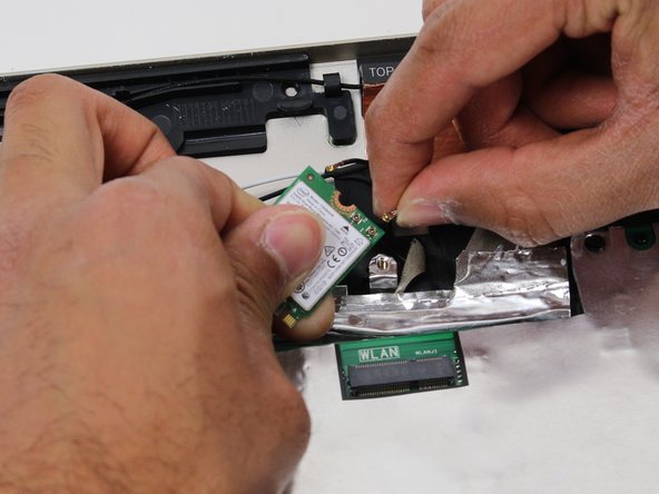
Locate the WLAN card in the upper left hand corner of the computer.
-
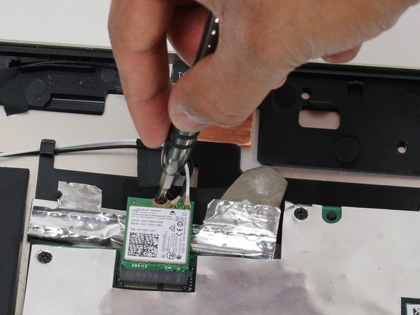
Use a Phillips #1 screwdriver to remove the 3.2 mm screw on the top of the WLAN card.
-
-
-
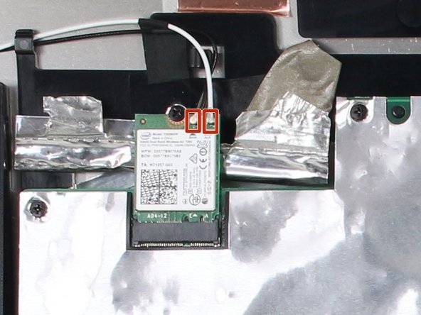
Pull out the WLAN card from its socket.
-
Remove the two antennae wires from the WLAN card by pulling up on the coaxial connectors.
-
-
-
Use a Phillips #0 screwdriver to remove the three (3) 4.8 mm screws from the fan unit.
-
Remove the cable connecting the fan to the motherboard by pulling the cable out of its socket.
-
-
-
Remove the fan by peeling off the black electrical tape holding it against the heat sink vents.
-
-
-
Remove the six (6) ribbon cables by lifting up on the plastic locking tabs and then slipping the cables out of their sockets.
-
Remove the other two (2) cables by pulling straight out on the white connectors.
-
-
-
Use a Phillips #1 screwdriver to remove nine (9) 3.2 mm screws from the motherboard.
-
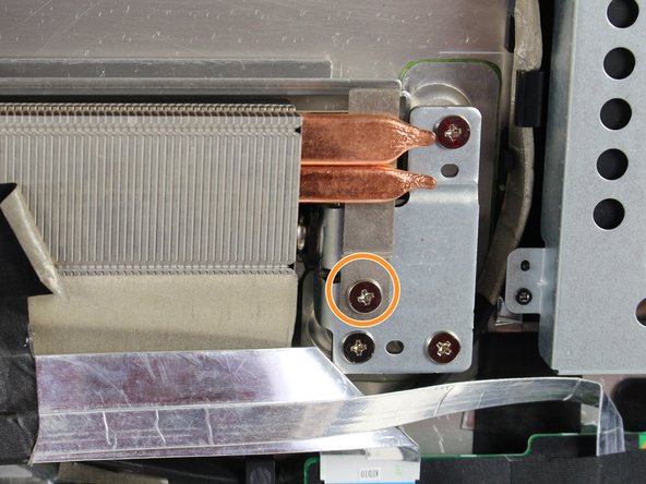
Use a Phillips #1 screwdriver to remove the one (1) 4.8 mm screw directly below the copper heat sink channel.
-
-
-
Lift the motherboard just enough to dismount it from the plastic pegs that hold it in place.
-
Rotate the motherboard towards yourself while supporting the heat sink by pivoting on its bottom edge.
-
-
-
Remove the SATA cable on the opposite side of the motherboard by pulling directly up from the board.
-
-
-
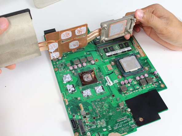
Use a Phillips #1 screwdriver to loosen the four (4) large silver screws evenly in the order of the numbers engraved next to each screw.
-
Use a Phillips # 0 to loosen the other four (4) 2.4 mm screws evenly in the order engraved on the copper next to each screw.
-
Repeat the last two bullets until all the larger silver screws make a clicking sound and the 2mm screws are removed.
-
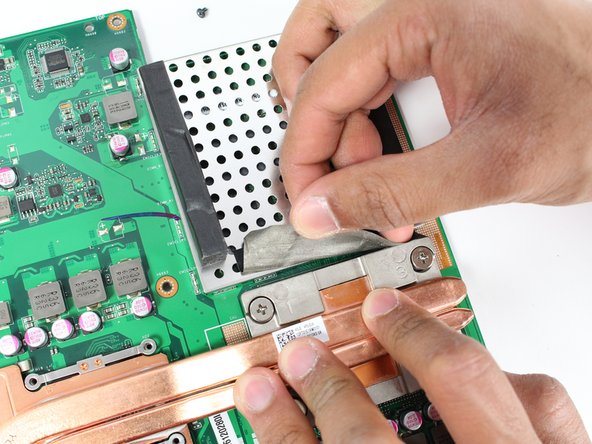
Peel away the black tape between the RAM shield and the heat sink.
-


To reassemble your device, follow these instructions in reverse order.
To reassemble your device, follow these instructions in reverse order.
Отменить: Я не выполнил это руководство.
Еще один человек закончил это руководство.
Команда

Cal Poly, Team S4-G1, Livingston Fall 2017 Участник Cal Poly, Team S4-G1, Livingston Fall 2017
CPSU-LIVINGSTON-F17S4G1
5 членов
Автор 25 руководств