Эта версия возможно содержит некорректные исправления. Переключить на последнюю проверенную версию.
Выберете то, что вам нужно
-
Этот шаг не переведен. Помогите перевести
-
Turn your Blackberry Storm 9500 onto its back side, and remove the battery door & battery.
-
-
Этот шаг не переведен. Помогите перевести
-
Remove the 2 screws (T6) under the battery compartment they are located as shown in red.
-
-
Этот шаг не переведен. Помогите перевести
-
Turn the Blackberry Storm 9500 around and pry off the microphone cover at the top using a safe pry tool.
-
-
-
Этот шаг не переведен. Помогите перевести
-
Flip it back over to the back of the phone, and remove the plastic lens on top of the camera & flash. This is held in place by some adhesive, so use a safe pry tool to remove as shown.
-
-
Этот шаг не переведен. Помогите перевести
-
Once the plastic piece is removed, unscrew the two torx screws underneath it.
-
-
Этот шаг не переведен. Помогите перевести
-
Now use a safe pry tool, and go along the edges of the phone to release the clips to open the housing. There are a total of 6 clips, 3 on each side.
-
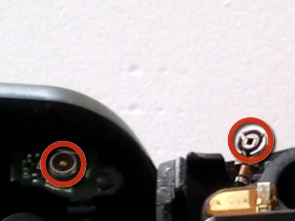
There is a small cap connection that connects the antenna to the logic board as pictured.
-
-
Этот шаг не переведен. Помогите перевести
-
Once you have worked you way all the way around the device with the safe pry tool you can now separate the two pieces of the housing.
-
*Be sure to remove the antenna cable in the top portion of the housing. You will need to reattach this when you repair the phone*
-
-
Этот шаг не переведен. Помогите перевести
-
Now remove the logic board & LCD assembly from the rear housing. Be gentle, and do not use excessive force.
-
-
Этот шаг не переведен. Помогите перевести
-
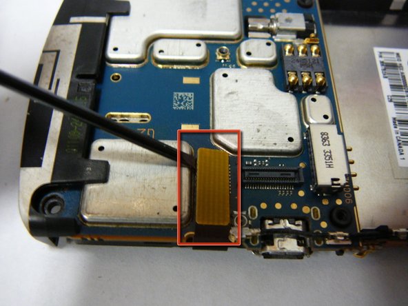
Flip the logicboard around so that it is sitting on top of the screen, now remove the two ribbon cables for the LCD & Digitizer.
-
-
Этот шаг не переведен. Помогите перевести
-
Put your broken assembly to the side, and now install your new one following the past steps in reverse.
-


Отменить: Я не выполнил это руководство.
13 участников успешно повторили данное руководство.
