Эта версия возможно содержит некорректные исправления. Переключить на последнюю проверенную версию.
Выберете то, что вам нужно
-
Этот шаг не переведен. Помогите перевести
-
Lay the computer face-down on a flat surface. Orient the computer to match the image.
-
Locate the battery release switch, as indicated in the image by the red rectangle. Slide the switch from right to left, and remove the battery.
-
-
Этот шаг не переведен. Помогите перевести
-
Locate the hard drive cover. Note that in this image, the RAM cover is still in place.
-
-
Этот шаг не переведен. Помогите перевести
-
Remove the two 5.0mm screws securing the hard drive bracket.
-
-
Этот шаг не переведен. Помогите перевести
-
Slide the hard drive to the right until the edge of the hard drive is flush with the computer frame.
-
Lift the hard drive out of the hard drive bay, left side first.
-
-
Этот шаг не переведен. Помогите перевести
-
Remove the two 5mm Phillips screws on the right side of the RAM cover.
-
Lift the right side of the RAM cover, and remove it.
-
-
Этот шаг не переведен. Помогите перевести
-
Release the RAM by pressing the metal heads of the RAM clips to the sides. Use tweezers and the spudger to spread the clips until they are completely off the RAM.
-
-
Этот шаг не переведен. Помогите перевести
-
As in step 3, press the clips on both sides to release the second RAM clip.
-
-
Этот шаг не переведен. Помогите перевести
-
Remove the 11.0mm screw securing the optical drive to the computer.
-
-
-
Этот шаг не переведен. Помогите перевести
-
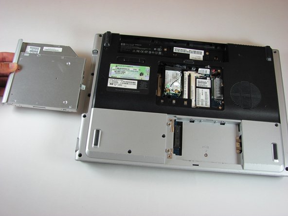
Locate the optical drive. The optical drive is located on the left side of the RAM bay.
-
Press the exposed edge of the optical drive gently with the spudger until the drive releases from the computer frame.
-
Pull the optical drive completely out of the computer frame.
-
-
Этот шаг не переведен. Помогите перевести
-
Disconnect the antenna leads from the wifi card by lifting the gold ends of the wires off the prongs on the wifi card.
-
The white wire connects to the AUX terminal.
-
The black wire connects to the MAIN terminal.
-
-
Этот шаг не переведен. Помогите перевести
-
Remove the two 6.0mm Phillips screws from the wifi card.
-
Remove the wifi card.
-
-
Этот шаг не переведен. Помогите перевести
-
Remove the two 11.0mm screws at the corners on either side of the battery compartment.
-
Remove the three 6.0mm screws.
-
Remove the two 5.0mm screws.
-
Remove the 6.0mm screw in the middle of the battery compartment.
-
-
Этот шаг не переведен. Помогите перевести
-
Turn the computer over and open the screen. This provides access to the screen hinges.
-
The keyboard switch cover is attached to the computer with a series of snaps. With a flathead screwdriver, pry up the switch cover until it pops free.
-
-
Этот шаг не переведен. Помогите перевести
-
Be careful not to bend the keyboard switch cover too far when removing it.
-
-
Этот шаг не переведен. Помогите перевести
-
Next, remove the keyboard. Push on the keyboard frame above the function keys and slide the keyboard toward the screen.
-
-
Этот шаг не переведен. Помогите перевести
-
Carefully lift the trackpad-side edge of the keyboard to reveal the LED and keyboard cable connectors.
-
Detach the cable connectors from the computer by gripping each cable connector close to the computer contact point and pulling up gently.
-
-
Этот шаг не переведен. Помогите перевести
-
Lay the keyboard face down.
-
Remove the four 3.00mm screws that attach the keyboard to the keyboard frame.
-
-
Этот шаг не переведен. Помогите перевести
-
Use the plastic prying tool to disconnect the screen cable from the system board.
-
-
Этот шаг не переведен. Помогите перевести
-
Remove the four 7.0mm screws securing the screen to the computer.
-
-
Этот шаг не переведен. Помогите перевести
-
Separate the screen from the computer frame by lifting the screen straight up.
-
Disconnect the PCI wires by pulling them free of the computer.
-
-
Этот шаг не переведен. Помогите перевести
-
Flip the computer over to access the screws on the underside of the frame.
-
Remove the two 3.0mm screws.
-
Remove the 5.0mm screw.
-
-
Этот шаг не переведен. Помогите перевести
-
Flip the computer over so the touchpad is accessible.
-
Disconnect the touchpad cable by pulling on it gently.
-
-
Этот шаг не переведен. Помогите перевести
-
Remove the three 5.0mm screws in the silver panel.
-
Remove the seven 10.0mm screws.
-
-
Этот шаг не переведен. Помогите перевести
-
Press gently on the textured front of the Express Card, then release it. It will pop out of the slot.
-
Remove the Express Card from the Express Card slot.
-
-
Этот шаг не переведен. Помогите перевести
-
Remove the 6.0mm screw that secures the display hinge support to the computer frame.
-
Remove the display hinge support.
-
Disconnect the power connector cable.
-
-
Этот шаг не переведен. Помогите перевести
-
Press gently on the front of the wireless card, then release it. It will pop out of the slot.
-
Remove the wireless card from the wireless card slot.
-
-
Этот шаг не переведен. Помогите перевести
-
Remove the 10.0mm screw.
-
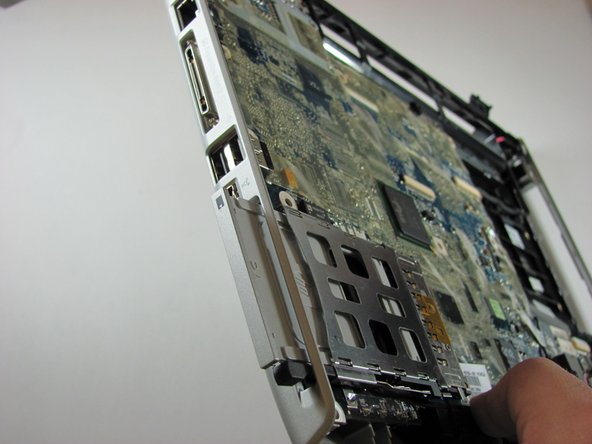
Remove the two 6.0mm screws securing the Express Card bracket.
-
Remove the Express Card bracket
-


Отменить: Я не выполнил это руководство.
8 участников успешно повторили данное руководство.
Команда

Cal Poly, Team 21-34, Regan Fall 2010 Участник Cal Poly, Team 21-34, Regan Fall 2010
CPSU-REGAN-F10S21G34
4 членов
Автор 11 руководств