Перейти к основному содержанию

Эта версия возможно содержит некорректные исправления. Переключить на последнюю проверенную версию.

Выберете то, что вам нужно

  1. Этот шаг не переведен. Помогите перевести

    : шаг 1, изображение 1 из 1
    • Flip over the device so that the bottom is facing you.

    • Locate the battery on the bottom of your laptop.

  2. Этот шаг не переведен. Помогите перевести

    : шаг 2, изображение 1 из 2 : шаг 2, изображение 2 из 2
    • Slide the tab all the way over to the left until battery pops out. Lift out and remove battery.

  3. Этот шаг не переведен. Помогите перевести

    : шаг 3, изображение 1 из 2 : шаг 3, изображение 2 из 2
    • Remove the RAM port cover by unscrewing the two screws.

    • These screws can not be fully removed because they’re captive. Loosen them until they turn freely.

  4. Этот шаг не переведен. Помогите перевести

    : шаг 4, изображение 1 из 2 : шаг 4, изображение 2 из 2
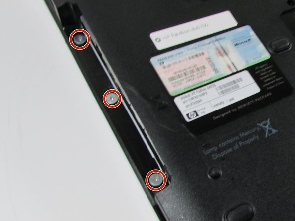
    • Use a Phillips #00 screwdriver to remove the two screws securing Hard Disk Drive (HDD) cover.

    • Screws will not fully remove. Loosen them until they turn freely.

  5. Этот шаг не переведен. Помогите перевести

    : шаг 5, изображение 1 из 3 : шаг 5, изображение 2 из 3 : шаг 5, изображение 3 из 3
    • Use a Phillips #00 screwdriver to remove the 25 screws securing the bottom of the computer.

  6. Этот шаг не переведен. Помогите перевести

    : шаг 6, изображение 1 из 3 : шаг 6, изображение 2 из 3 : шаг 6, изображение 3 из 3
    • Detach WiFi antenna wires.

    • Be sure that the wires are labeled so you remember which ones go where.

  7. Этот шаг не переведен. Помогите перевести

    : шаг 7, изображение 1 из 3 : шаг 7, изображение 2 из 3 : шаг 7, изображение 3 из 3
    • Using the Phillips #0 screwdriver remove the 2 screws.

    • Use a needle-nose pliers to do the initial loosening, then switch to using a hex screwdriver (size 5) head to do the rest of the loosening.

  8. Этот шаг не переведен. Помогите перевести

    : шаг 8, изображение 1 из 2 : шаг 8, изображение 2 из 2
    • Flip over HP Pavilion dv6700 so that the top is facing you.

    • Open up HP Pavilion dv6700.

  9. Этот шаг не переведен. Помогите перевести

    : шаг 9, изображение 1 из 3 : шаг 9, изображение 2 из 3 : шаг 9, изображение 3 из 3
    • Use an iFixit opening tool to pry open the plastic bar above the keyboard.

    • Be careful not to yank so hard that you rip out the ribbon cables underneath. There is enough room to pull safely, but use control to prevent damage.

  10. Этот шаг не переведен. Помогите перевести

    : шаг 10, изображение 1 из 3 : шаг 10, изображение 2 из 3 : шаг 10, изображение 3 из 3
    • Pull out and up on keyboard to remove it.

    • Do not yank it all of the way out, as there is a ribbon cable underneath.

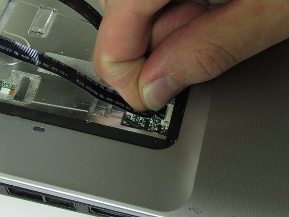
    • Slide the two black locks on the side of the keyboard cable connection port up to release the cable.

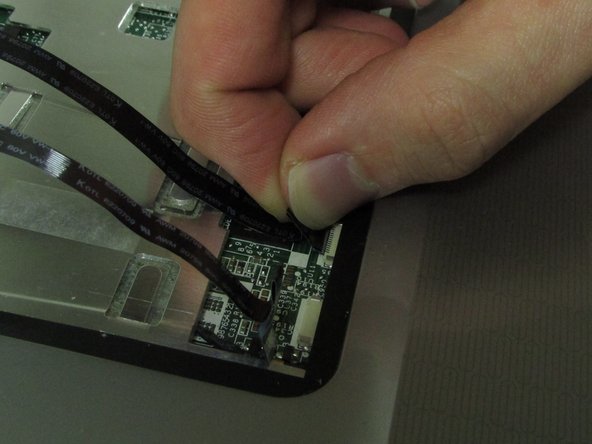
    • Grip the ribbon cable near the connection point and gently but firmly pull it out.

  11. Этот шаг не переведен. Помогите перевести

    : шаг 11, изображение 1 из 2 : шаг 11, изображение 2 из 2
    • Flip over the plastic bar.

    • Detach the display connector.

    • Do not pull on the wires. Pull on the black plastic part or wedge an iFixit opening tool or fingernail between the port and the connector.

  12. Этот шаг не переведен. Помогите перевести

    : шаг 12, изображение 1 из 3 : шаг 12, изображение 2 из 3 : шаг 12, изображение 3 из 3
    • Detach the ribbon cables.

    • Pull from the area closest to the connection port gently but firmly.

  13. Этот шаг не переведен. Помогите перевести

    : шаг 13, изображение 1 из 3 : шаг 13, изображение 2 из 3 : шаг 13, изображение 3 из 3
    • Pull up on tape holding down wires.

  14. Этот шаг не переведен. Помогите перевести

    : шаг 14, изображение 1 из 3 : шаг 14, изображение 2 из 3 : шаг 14, изображение 3 из 3
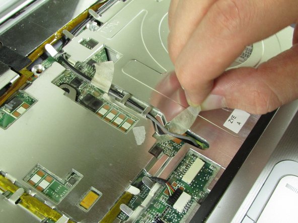
    • Pull up on the WiFi wires and out from under the metal tabs.

    • Do not yank them out. Let them hang loose once they are out from under the tabs.

  15. Этот шаг не переведен. Помогите перевести

    : шаг 15, изображение 1 из 3 : шаг 15, изображение 2 из 3 : шаг 15, изображение 3 из 3
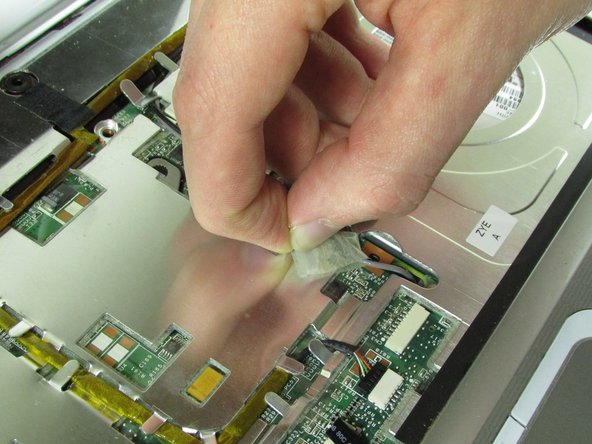
    • Disconnect the connector from the port.

    • Remove the wire from under the metal tabs.

    • Let wire hang loose after removing under the tabs.

  16. Этот шаг не переведен. Помогите перевести

    : шаг 16, изображение 1 из 2 : шаг 16, изображение 2 из 2
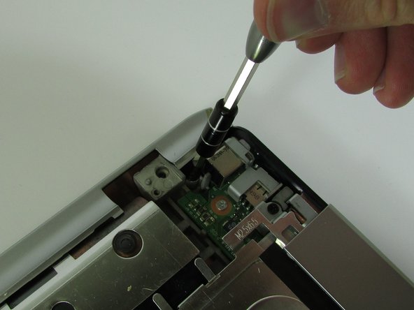
    • Use a Phillips #00 screwdriver to remove the black screw located in the top right corner near the display.

  17. Этот шаг не переведен. Помогите перевести

    : шаг 17, изображение 1 из 2 : шаг 17, изображение 2 из 2
    • Pull upward on the screen connector tab.

    • It will be firmly secured, so don't be afraid to use a little extra force to pull it off.

  18. Этот шаг не переведен. Помогите перевести

    : шаг 18, изображение 1 из 2 : шаг 18, изображение 2 из 2
    • Use a Phillips #00 screwdriver to remove the black screw securing the screen.

    • Keep your hand on the screen to secure it, as once you remove this screw, it will come loose.

    • Lift the screen off and set it aside.

  19. Этот шаг не переведен. Помогите перевести

    : шаг 19, изображение 1 из 3 : шаг 19, изображение 2 из 3 : шаг 19, изображение 3 из 3
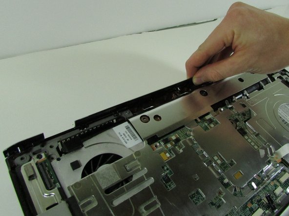
    • Unscrew the black screw in the top right corner using the Phillips #00 screwdriver.

    • Pull up on the top piece and remove it.

  20. Этот шаг не переведен. Помогите перевести

    : шаг 20, изображение 1 из 3 : шаг 20, изображение 2 из 3 : шаг 20, изображение 3 из 3
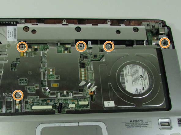
    • Remove the screw in top left corner using the Phillips #00 screwdriver

    • Remove the five screws that are located on the motherboard cover.

    • Pull up on the cover to remove it.

    • You can use a plastic opener if it is hard to get your fingers under the cover's edges.

    • Do not pull hard on the cover, as there are two ribbon cables under the cover connected to the motherboard.

  21. Этот шаг не переведен. Помогите перевести

    : шаг 21, изображение 1 из 3 : шаг 21, изображение 2 из 3 : шаг 21, изображение 3 из 3
    • Pull gently but firmly on the ribbon cables at the connection points to remove them

  22. Этот шаг не переведен. Помогите перевести

    : шаг 22, изображение 1 из 3 : шаг 22, изображение 2 из 3 : шаг 22, изображение 3 из 3
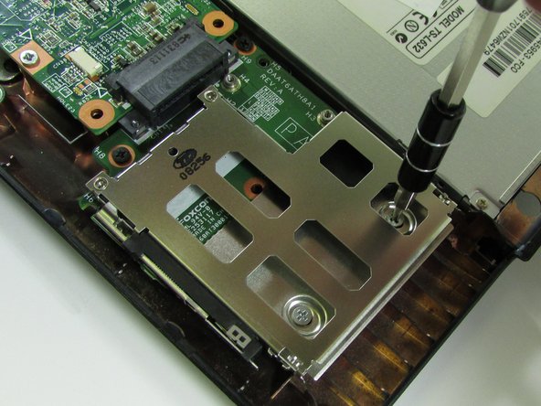
    • Remove the four screws from the ExpressCard component using the Phillips #00 screwdriver.

  23. Этот шаг не переведен. Помогите перевести

    : шаг 23, изображение 1 из 3 : шаг 23, изображение 2 из 3 : шаг 23, изображение 3 из 3
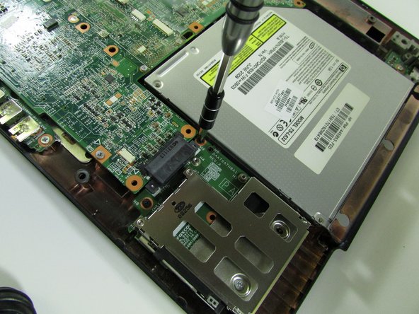
    • Remove ExpressCard component by sliding it out.

    • Remove Optical Drive by sliding it out.

  24. Этот шаг не переведен. Помогите перевести

    : шаг 24, изображение 1 из 2 : шаг 24, изображение 2 из 2
    • Detach connector from the motherboard.

    • This piece is likely to be very hard to disconnect, so do not be afraid to use more force than normal.

  25. Этот шаг не переведен. Помогите перевести

    : шаг 25, изображение 1 из 1
    • Using the Phillips #00 screwdriver, remove the one screw near where the ExpressCard component was.

  26. Этот шаг не переведен. Помогите перевести

    : шаг 26, изображение 1 из 3 : шаг 26, изображение 2 из 3 : шаг 26, изображение 3 из 3
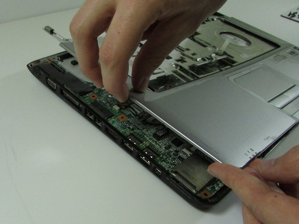
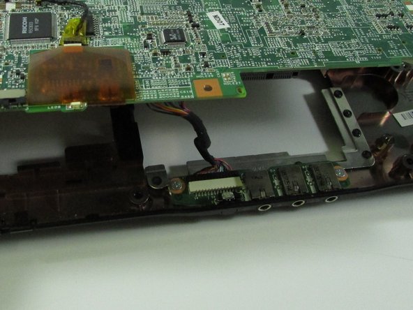
    • Lift up motherboard.

    • Detach the motherboard connector at the front under the motherboard.

  27. Этот шаг не переведен. Помогите перевести

    : шаг 27, изображение 1 из 3 : шаг 27, изображение 2 из 3 : шаг 27, изображение 3 из 3
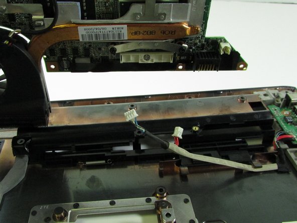
    • Lift up and out the motherboard.

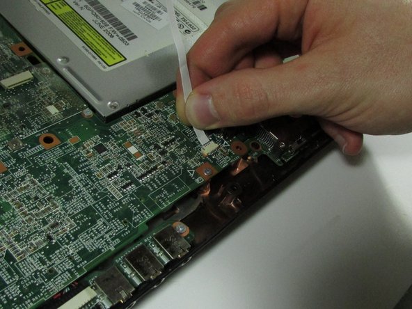
    • Detach the connector under the motherboard.

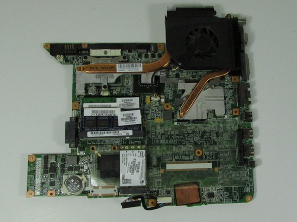
    • Remove the motherboard.

Финишная черта

8 участников успешно повторили данное руководство.

Alec Gramm

Участник с: 10/01/15

1 228 Репутация

Автор 5 руководств

Команда

2 Комментариев

Brilliant presentation.

Great Help

Thanks

ivor - Ответить

Thank you for all your help . Very decent of you.

Spot on guide and detail.

Ian, Poynton< Cheshire

UK.

558vulcanxh - Ответить

Добавить комментарий

Просмотр статистики:

За последние 24часов: 2

За последние 7 дней: 8

За последние 30 дней: 12

За всё время: 3,382