Эта версия возможно содержит некорректные исправления. Переключить на последнюю проверенную версию.
Выберете то, что вам нужно
-
Этот шаг не переведен. Помогите перевести
-
Apply pressure along the bottom of the white panel containing the camera and push upwards.
-
-
Этот шаг не переведен. Помогите перевести
-
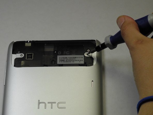
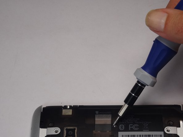
Unscrew the four of 3.5mm Torx T5 screws that run along the sides of the exposed innards.
-
-
Этот шаг не переведен. Помогите перевести
-
Remove the black protective piece of plastic by sliding it upwards.
-
Remove the two 3.5mm Torx #5 screws holding the protective plastic down on along the sides.
-
Either remove the sticker or jam the screwdriver into the screw, and remove the screw.
-
Remove the protective panel by sliding it upwards.
-
-
Этот шаг не переведен. Помогите перевести
-
Before removing the back cover, apply some scotch tape to the volume buttons to prevent them from falling out of the back panel.
-
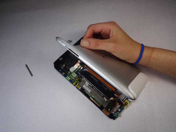
Use a plastic opening tool to lever up the top half of the cover.
-
Lift the back panel up and remove it from the device.
-
-
Этот шаг не переведен. Помогите перевести
-
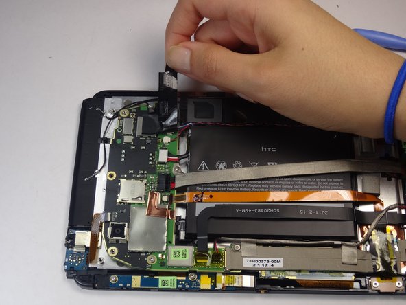
Gently unfold the black tape along the top that covers the cable attachment points.
-
-
Этот шаг не переведен. Помогите перевести
-
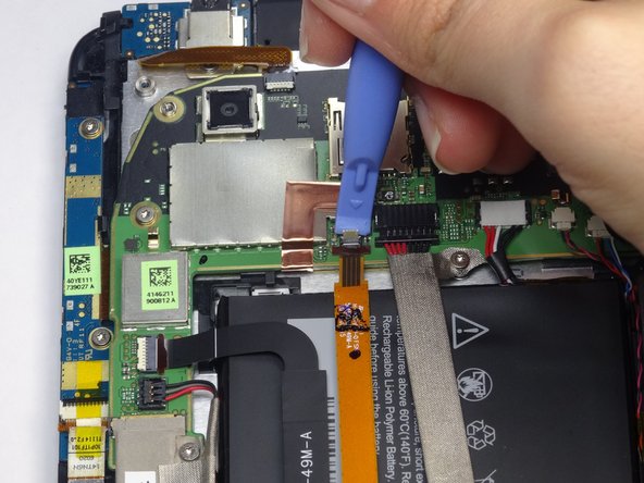
Use the tip of a spudger as a lever to disconnect the four cable connectors.
-
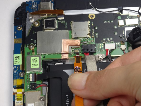
Gently pull out these cables after releasing the back piece.
-
-
Этот шаг не переведен. Помогите перевести
-
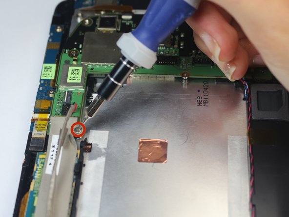
Remove the single 2.5mm Torx T5 screw holding the battery down along the top side.
-
-
Этот шаг не переведен. Помогите перевести
-
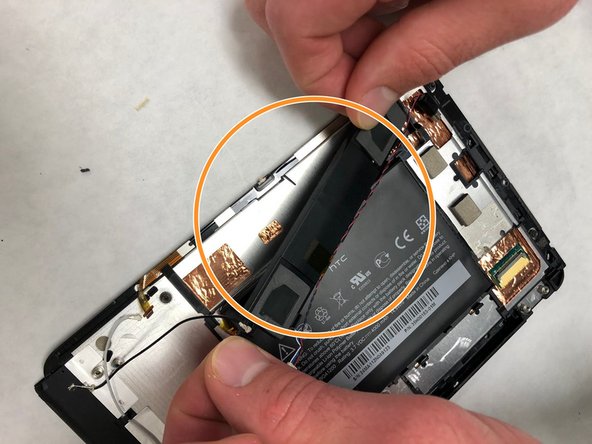
Wedge the flat end of a spudger inbetween the battery and the front panel assembly.
-
Run the flat end of a spudger along the top edge of the battery to separate it from the adhesive securing it to the front panel assembly.
-
-
-
Этот шаг не переведен. Помогите перевести
-
Remove the four 2.5mm Torx #5 screws that run along the motherboard's rim.
-
-
Этот шаг не переведен. Помогите перевести
-
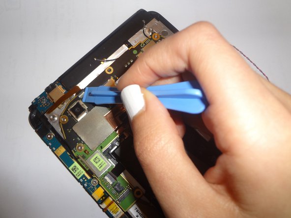
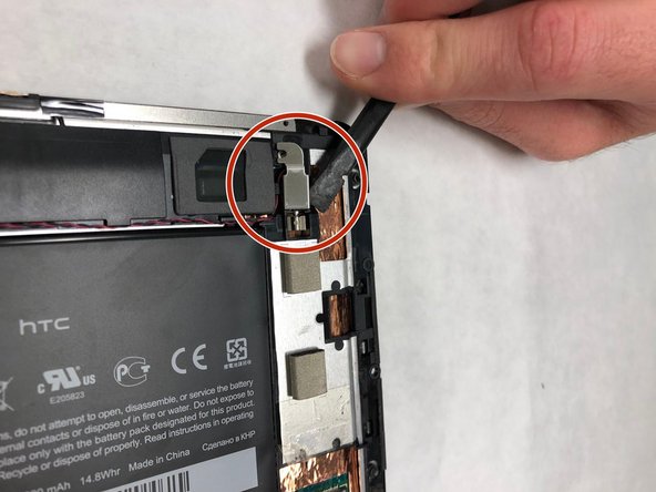
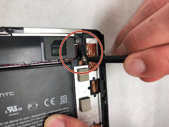
Use a spudger to remove the two black ground wires from the right side of the motherboard.
-
Remove the two multicolored speaker cables on the right side by lifting up the "lever" on the opposite side of the cable socket and then pulling out the cables.
-
-
Этот шаг не переведен. Помогите перевести
-
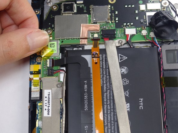
Lift up the translucent yellow tape to expose the cable sockets.
-
Use the spudger to lift up the cable's "lever".
-
Pull out the cables.
-
-
Этот шаг не переведен. Помогите перевести
-
Remove the cable along the headphone in the same way the lower cables were removed.
-
-
Этот шаг не переведен. Помогите перевести
-
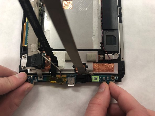
Remove lower flex cable and LCD flex cable. They are attached and will be removed as one piece.
-
-
Этот шаг не переведен. Помогите перевести
-
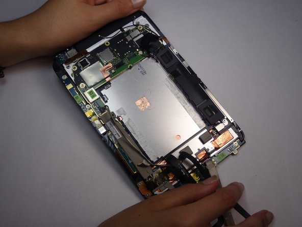
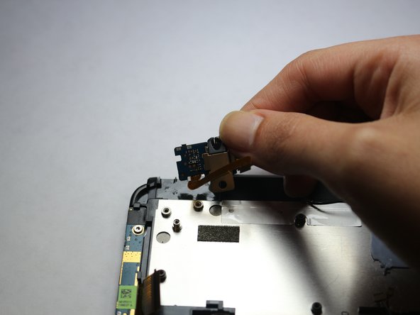
Lift away vibrate motor.
-
Lift away speaker assembly. They should be attached and will be removed as one piece.
-
-
Этот шаг не переведен. Помогите перевести
-
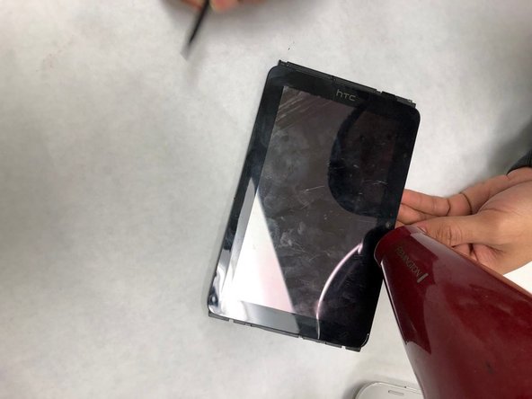
Flip tablet and use hairdryer to heat the outside edges of the screen. Heat the edges for about 45 seconds using quick arm movement with the hair dryer set to high.
-
Heat for longer if necessary.
-
-
Этот шаг не переведен. Помогите перевести
-
Release the adhesive around the edges of the screen with a safe open pry tool. Continue to reheat the adhesive as needed.
-
-
Этот шаг не переведен. Помогите перевести
-
Slide the flex cable through the slot in the housing to its left.
-
-
Этот шаг не переведен. Помогите перевести
-
Replace the touch screen digitizer. It is the black rectangle circled in the picture
-


Команда

IUPUI, Team S5-G5, Wilson Fall 2018 Участник IUPUI, Team S5-G5, Wilson Fall 2018
IUPUI-WILSON-F18S5G5
4 членов
Автор 3 руководств