Эта версия возможно содержит некорректные исправления. Переключить на последнюю проверенную версию.
Выберете то, что вам нужно
-
Этот шаг не переведен. Помогите перевести
-
Begin by removing the rubber caps on both sides of the JBL Flip 2 by using the black spudger to get in between the creases.
-
-
Этот шаг не переведен. Помогите перевести
-
Remove the eight 7.0 mm Phillips #1 screws on both sides of the JBL Flip 2.
-
-
Этот шаг не переведен. Помогите перевести
-
The NFC chip is glued onto the side of the device. Use the black spudger to separate the mic from the surface.
-
Gently slide the NFC chip into the device through the slot that the wire comes from.
-
-
Этот шаг не переведен. Помогите перевести
-
Remove the two 7.0 mm Phillips #1 screws.
-
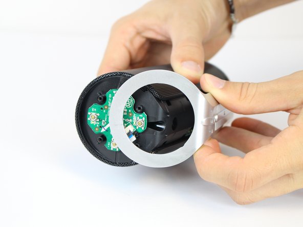
Carefully detach the silver plastic cover by pulling both ends off.
-
Separate the silver plastic piece by pulling it off from the middle.
-
-
-
Этот шаг не переведен. Помогите перевести
-
Using a flat-head screwdriver or spudger, pry out the 8 metal nibs on the back side of the speaker.
-
Repeat the same process for the 4 remaining metal nibs (two on each end).
-
-
Этот шаг не переведен. Помогите перевести
-
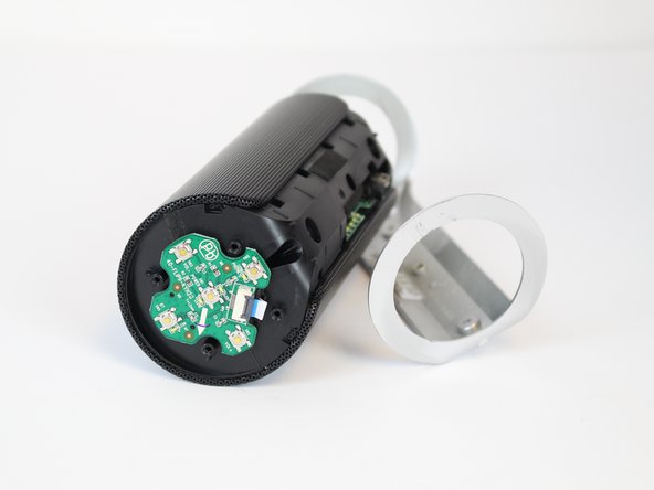
Expand the metal casing and carefully slide it off the speaker.
-
-
Этот шаг не переведен. Помогите перевести
-
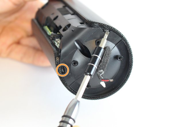
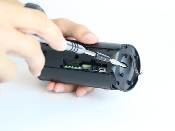
Using the driver adapter, first insert the #4 socket into the driver; followed by the #1 Philip's head bit in order to reach the three 13.0 mm screws.
-
-
Этот шаг не переведен. Помогите перевести
-
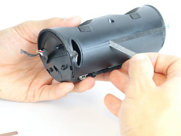
Using the classic spudger, get underneath the black tape strips found on both side of the device.
-
After lifting a portion of the tape off of the device, gently peel the tape off of the device, making sure to keep it intact.
-
There is another piece of tape on the side of the device with the control buttons. Lift the tape with the classic spudger and then peel the rest of the tape off.
-
-
Этот шаг не переведен. Помогите перевести
-
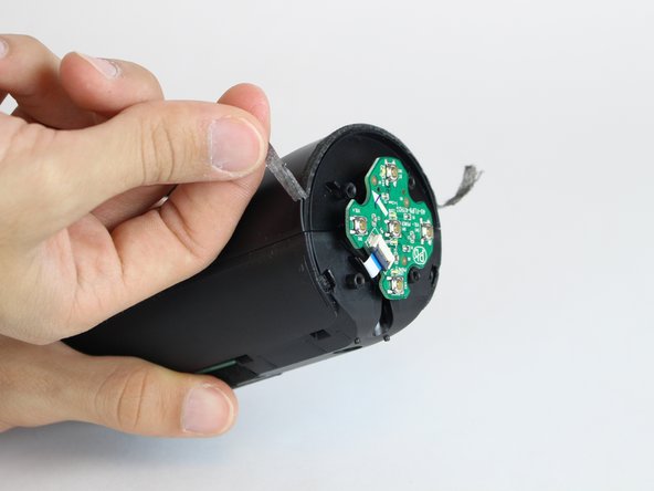
Wedge a spudger between the two halves where the tape was to pry the device open.
-
-
Этот шаг не переведен. Помогите перевести
-
Use the black spudger to disconnect the speaker cord from it's socket.
-
-
Этот шаг не переведен. Помогите перевести
-
Use the black spudger to disconnect the auxiliary wire from its socket.
-
-
Этот шаг не переведен. Помогите перевести
-
Carefully remove the cable connecting the control chip to the motherboard.
-
-
Этот шаг не переведен. Помогите перевести
-
Using the black spudger, carefully remove the cord connecting the battery to the motherboard.
-
-
Этот шаг не переведен. Помогите перевести
-
Carefully remove the cable connecting the nfc chip to the motherboard.
-


Команда

USF Tampa, Team 11-2, Cheng Spring 2016 Участник USF Tampa, Team 11-2, Cheng Spring 2016
USFT-CHENG-S16S11G2
4 членов
Автор 8 руководств