Перейти к основному содержанию

Эта версия возможно содержит некорректные исправления. Переключить на последнюю проверенную версию.

Выберете то, что вам нужно

  1. Этот шаг не переведен. Помогите перевести

    : шаг 1, изображение 1 из 2 : шаг 1, изображение 2 из 2
    • Unscrew the four 3.5mm side screws with a Phillips #1 screwdriver.

    • There are two screws per side.

  2. Этот шаг не переведен. Помогите перевести

    : шаг 2, изображение 1 из 3 : шаг 2, изображение 2 из 3 : шаг 2, изображение 3 из 3
    • Use a spudger to unhook the plastic clips on the sides and top of the front panel. There are two clips on each side and one clip on the top.

    • Place the spudger between the plastic tab and the metal case and gently lift the spudger away from the case.

  3. Этот шаг не переведен. Помогите перевести

    : шаг 3, изображение 1 из 1
    • Pull the top of the front panel out and down to remove front panel.

    • Remove the front panel gently so as not to damage the ribbon cables behind it.

  4. Этот шаг не переведен. Помогите перевести

    : шаг 4, изображение 1 из 3 : шаг 4, изображение 2 из 3 : шаг 4, изображение 3 из 3
    • Unscrew the three 5mm screws from the top of the device using a Phillips #1 screwdriver.

    • Lift up to remove the top casing.

  5. Этот шаг не переведен. Помогите перевести

    : шаг 5, изображение 1 из 1
    • Lift the CD drive carefully to expose the attached cable underneath.

  6. Этот шаг не переведен. Помогите перевести

    : шаг 6, изображение 1 из 2 : шаг 6, изображение 2 из 2
    • Flip up the black clasp with a spudger to disconnect the large white ribbon cable connecting the CD drive to the board underneath.

  7. Этот шаг не переведен. Помогите перевести

    : шаг 7, изображение 1 из 1
    • Carefully unplug the fan power cord with the tweezers.

  8. Этот шаг не переведен. Помогите перевести

    : шаг 8, изображение 1 из 2 : шаг 8, изображение 2 из 2
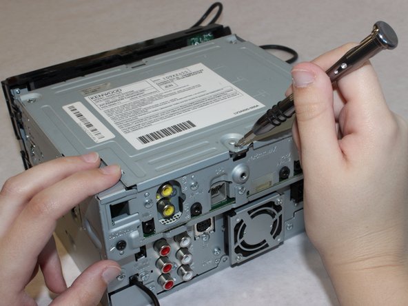
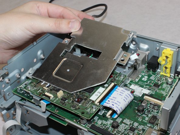
    • Unscrew the three 5mm length screws with the Phillips #1 screwdriver.

    • Remove the metal plate

    • Removing the plate will damage the heat sink compound. This will need to be replaced during reassembly.

  9. Этот шаг не переведен. Помогите перевести

    : шаг 9, изображение 1 из 2 : шаг 9, изображение 2 из 2
    • Unscrew the three 5.5mm long screws with a Phillips #1 screwdriver.

  10. Этот шаг не переведен. Помогите перевести

    : шаг 10, изображение 1 из 3 : шаг 10, изображение 2 из 3 : шаг 10, изображение 3 из 3
    • Remove the four 5.5mm screws with the Phillips #1 screwdriver.

  11. Этот шаг не переведен. Помогите перевести

    : шаг 11, изображение 1 из 1
    • Lift the top part of the unit up from the lower chassis.

  12. Этот шаг не переведен. Помогите перевести

    : шаг 12, изображение 1 из 2 : шаг 12, изображение 2 из 2
    • Remove the two 13mm long screws with a Phillips #1 screwdriver.

    • Gently thread the power cable through the circuit boards to separate the fan from the body of the stereo.

  13. Этот шаг не переведен. Помогите перевести

    : шаг 13, изображение 1 из 2 : шаг 13, изображение 2 из 2
    • Using a spudger, undo the clasp to disconnect the large white ribbon cable.

  14. Этот шаг не переведен. Помогите перевести

    : шаг 14, изображение 1 из 1
    • Remove the 5mm screw with teeth from the casing with a Phillips #1 screwdriver.

  15. Этот шаг не переведен. Помогите перевести

    : шаг 15, изображение 1 из 1
    • Remove the four 5mm screws with a Phillips #1 screwdriver.

  16. Этот шаг не переведен. Помогите перевести

    : шаг 16, изображение 1 из 2 : шаг 16, изображение 2 из 2
    • Remove the 5.5mm screw from the HDMI cable cover using a Phillips #2 screwdriver.

  17. Этот шаг не переведен. Помогите перевести

    : шаг 17, изображение 1 из 1
    • Remove the 5mm screw with a Phillips #1 screwdriver.

  18. Этот шаг не переведен. Помогите перевести

    : шаг 18, изображение 1 из 2 : шаг 18, изображение 2 из 2
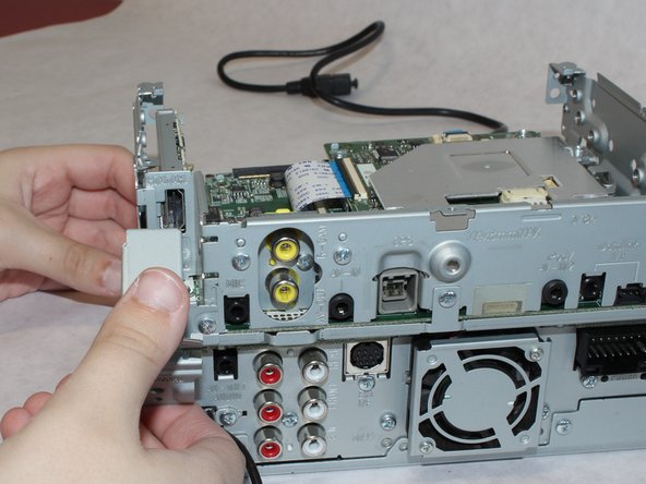
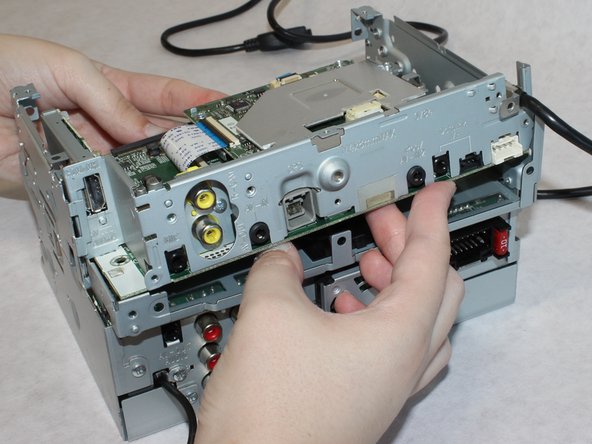
    • Remove the two 5.5mm screws from the back.

    • Lift the upper portion of the stereo free from the chassis.

  19. Этот шаг не переведен. Помогите перевести

    : шаг 19, изображение 1 из 2 : шаг 19, изображение 2 из 2
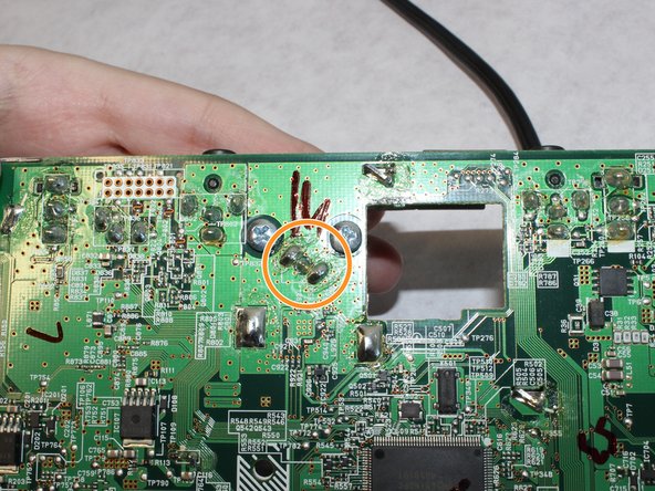
    • Remove the two screws underneath the GPS connector.

    • Desolder the GPS connector.

    • The GPS antenna is a thru-hole-mounted device. You must apply heat to each soldered pin individually and pull them out of the holes while the solder is molten.

    • The solder material, pins, and any surrounding material will get VERY hot while melting the connections. Do not touch any metal parts during the desoldering process and give the device time to cool off once you’re finished. It may also be good to take breaks so that the electronics aren’t kept hot for extended periods of time.

  20. Этот шаг не переведен. Помогите перевести

    : шаг 20, изображение 1 из 1
    • To remove and reinsert the connector, on the top side of the board, use your finger to gently lift the metal plate to get enough clearance.

Финишная черта

Еще один человек закончил это руководство.

Wendy Zaballos

Участник с: 09/17/18

952 Репутация

Автор 6 руководств

Команда

Washington State, Team S1-G1, Hope Fall 2018 Участник Washington State, Team S1-G1, Hope Fall 2018

WSU-HOPE-F18S1G1

4 членов

Автор 6 руководств

0 Комментариев

Добавить комментарий

Просмотр статистики:

За последние 24часов: 1

За последние 7 дней: 6

За последние 30 дней: 14

За всё время: 851