Эта версия возможно содержит некорректные исправления. Переключить на последнюю проверенную версию.
Выберете то, что вам нужно
-
Этот шаг не переведен. Помогите перевести
-
Using a Phillips #0 screwdriver, remove the seven 7mm screws holding the back cover onto your computer.
-
-
Этот шаг не переведен. Помогите перевести
-
Use a plastic opening tool or your fingers to pry off the cover.
-
-
Этот шаг не переведен. Помогите перевести
-
Using your fingers, disconnect the battery from the motherboard.
-
-
Этот шаг не переведен. Помогите перевести
-
Using a Phillips #0 screwdriver, unscrew the five 4.3mm screws attaching the battery to the computer.
-
-
Этот шаг не переведен. Помогите перевести
-
Use a Phillips #1 screwdriver to undo the four 5 mm screws attached to the heat sink.
-
-
-
Этот шаг не переведен. Помогите перевести
-
Undo the black clasp that holds the ribbon cable, attached to the fan, in place and disconnect the ribbon cable.
-
-
Этот шаг не переведен. Помогите перевести
-
Disconnect all 10 of the ribbon cables attached to the motherboard.
-
-
Этот шаг не переведен. Помогите перевести
-
Disconnect the wire connecting the motherboard to the speaker.
-
-
Этот шаг не переведен. Помогите перевести
-
Use a Phillips #1 screwdriver to unscrew the 4mm screw holding the metal covering over the power jack prongs.
-
-
Этот шаг не переведен. Помогите перевести
-
Use a Phillips #1 screwdriver to unscrew the 4mm screw holding down the Micro-SD card tray.
-
-
Этот шаг не переведен. Помогите перевести
-
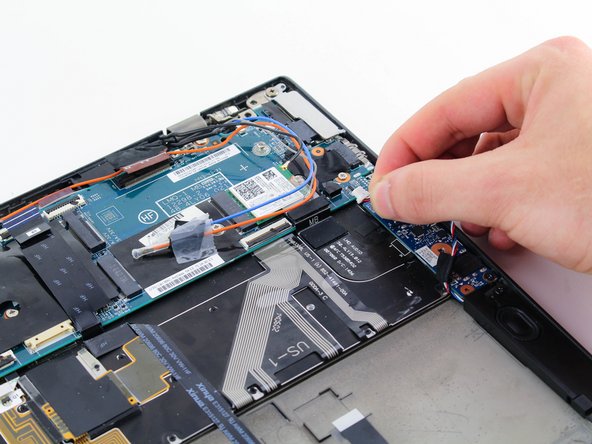
Remove the black and grey wires from the cable comb on the motherboard.
-
-
Этот шаг не переведен. Помогите перевести
-
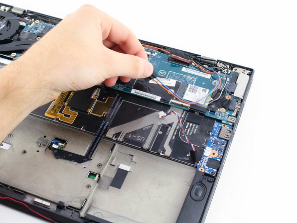
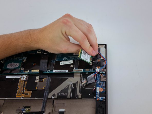
Use a Phillips #1 screwdriver to unscrew the 3.7mm screw holding down the wifi card.
-
Remove the wifi card.
-
-
Этот шаг не переведен. Помогите перевести
-
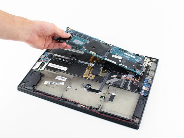
Carefully remove the motherboard by lifting it and pulling towards the left.
-


Отменить: Я не выполнил это руководство.
4 участников успешно повторили данное руководство.

Команда

Cal Poly, Team S18-G4, White Winter 2020 Участник Cal Poly, Team S18-G4, White Winter 2020
CPSU-WHITE-W20S18G4
4 членов
Автор 7 руководств
2 Комментариев
All going as described, until the final step trying to pull the motherboard out, and there is something still holding it in place. With a bit of a wiggle and pull, there is something about near the screw hole that was holding the wifi card down preventing the card from lifting there. Any clues?
Answering my own question: Removing the motherboard requires that you first pop the SIM card / MicroSD card holder out of the socket, otherwise it won’t lift out. Submitted an update to the guide to save others falling into the same trap.