Перейти к основному содержанию

Logic Board Disconnection

Абсолютно необходимое руководство
Это руководство предназначено только для использования в качестве обязательного условия для других руководств. Оно не полностью само по себе.

Выберете то, что вам нужно

  1. Logic Board Disconnection, Disconnect the logic board: шаг 1, изображение 1 из 2 Logic Board Disconnection, Disconnect the logic board: шаг 1, изображение 2 из 2
    • Use a T3 Torx driver to remove the two 1.4 mm screws securing the trackpad connector bracket.

    • Depending on the condition of your bits, a T4 Torx driver may fit better.

    • Remove the trackpad connector bracket.

  2. Logic Board Disconnection: шаг 2, изображение 1 из 2 Logic Board Disconnection: шаг 2, изображение 2 из 2
    • Use the flat end of a spudger to pry the trackpad cable connector up and out of its socket.

  3. Logic Board Disconnection: шаг 3, изображение 1 из 3 Logic Board Disconnection: шаг 3, изображение 2 из 3 Logic Board Disconnection: шаг 3, изображение 3 из 3
    • If the left speaker is already disconnected, skip this step.

    • Slide the tip of a spudger underneath the left speaker cable and pry straight up to disconnect the speaker.

    • With the connector disconnected, slide the flat end of a spudger under the cable to separate the adhesive securing the cable to the logic board.

  4. Logic Board Disconnection: шаг 4, изображение 1 из 2 Logic Board Disconnection: шаг 4, изображение 2 из 2
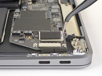
    • Use a T3 Torx driver to remove the two 1.3 mm screws securing the USB-C port connector bracket.

    • Remove the USB-C connector bracket.

  5. Logic Board Disconnection: шаг 5, изображение 1 из 2 Logic Board Disconnection: шаг 5, изображение 2 из 2
    • Use the flat end of a spudger to pry the USB-C cable connector up and out of its socket on the logic board.

  6. Logic Board Disconnection: шаг 6, изображение 1 из 3 Logic Board Disconnection: шаг 6, изображение 2 из 3 Logic Board Disconnection: шаг 6, изображение 3 из 3
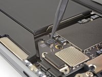
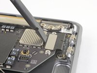
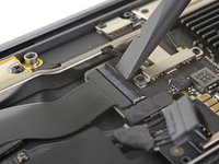
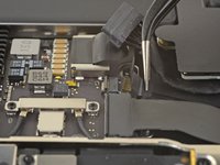
    • Use a spudger to lift up the small locking flap on the sound board cable's ZIF connector.

    • Slide the sound board cable out of the ZIF connector.

  7. Logic Board Disconnection: шаг 7, изображение 1 из 1
    • Peel back the black tape covering the fan cable connector.

  8. Logic Board Disconnection: шаг 8, изображение 1 из 3 Logic Board Disconnection: шаг 8, изображение 2 из 3 Logic Board Disconnection: шаг 8, изображение 3 из 3
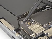
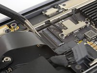
    • Use the tip of a spudger to lift up the locking flap on the fan cable's ZIF connector.

    • Slide the fan cable out of the ZIF connector.

  9. Logic Board Disconnection: шаг 9, изображение 1 из 2 Logic Board Disconnection: шаг 9, изображение 2 из 2
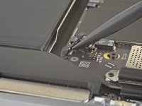
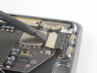
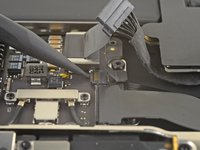
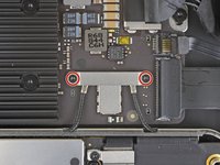
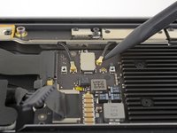
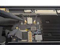
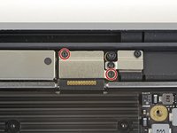
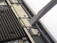
    • Use a T3 Torx driver to remove the two 1.4 mm screws securing the antenna cable bracket.

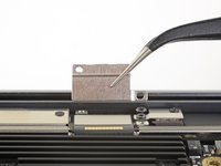
    • Remove the antenna cable bracket.

  10. Logic Board Disconnection: шаг 10, изображение 1 из 3 Logic Board Disconnection: шаг 10, изображение 2 из 3 Logic Board Disconnection: шаг 10, изображение 3 из 3
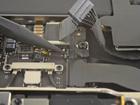
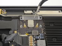
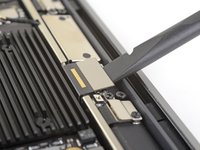
    • Insert the point of a spudger under one of the antenna cables close to the connector. Pry straight up to disconnect the cable.

    • Repeat for the other antenna cable.

  11. Logic Board Disconnection: шаг 11, изображение 1 из 2 Logic Board Disconnection: шаг 11, изображение 2 из 2
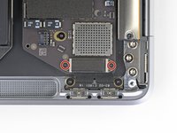
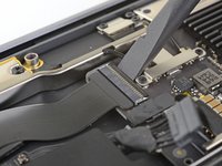
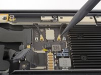
    • Use a T3 Torx driver to remove the two 1.5 mm screws securing the display cable connector bracket.

    • Remove the display cable connector bracket.

  12. Logic Board Disconnection: шаг 12, изображение 1 из 2 Logic Board Disconnection: шаг 12, изображение 2 из 2
    • Use the flat end of a spudger to pry up the display cable connector.

Заключение

To reassemble your device, follow these instructions in reverse order.

Adam O'Camb

Участник с: 04/11/15

196 299 Репутация

Автор 416 руководств

0 Комментариев

Добавить комментарий

Просмотр статистики:

За последние 24часов: 0

За последние 7 дней: 0

За последние 30 дней: 1

За всё время: 116