Эта версия возможно содержит некорректные исправления. Переключить на последнюю проверенную версию.
Выберете то, что вам нужно
-
Этот шаг не переведен. Помогите перевести
-
To get into the controller, you will need to unscrew the 7 screws on the back.
-
-
Этот шаг не переведен. Помогите перевести
-
With the screws removed, turn the controller upside down and separate the front end from the back end.
-
-
Этот шаг не переведен. Помогите перевести
-
There should be 4 circular buttons labeled 1-4, 4 smaller circular buttons for the D-Pad, and 3 oval shaped buttons.
-
-
-
Этот шаг не переведен. Помогите перевести
-
In the center of the controller, pull upwards on the USB cord.
-
With the wire out of the way, remove the screw it exposed. This will disconnect the logic board from the controller.
-
-
Этот шаг не переведен. Помогите перевести
-
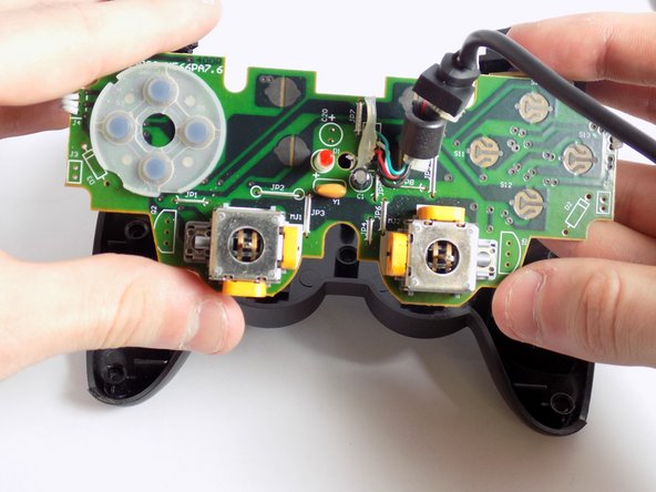
To remove the triggers, push upwards from the back on them.
-
Once far enough, detach the logic board from the back cover piece and the triggers.
-
-
Этот шаг не переведен. Помогите перевести
-
If the wire is unplugged solely from the logic board, you can fasten it back into its place.
-
Look at the second picture to see where the wires go.
-
-
Этот шаг не переведен. Помогите перевести
-
Unscrew the screw on the trigger to remove the back cover.
-
Once removed, carefully pull the back cover off.
-
-
Этот шаг не переведен. Помогите перевести
-
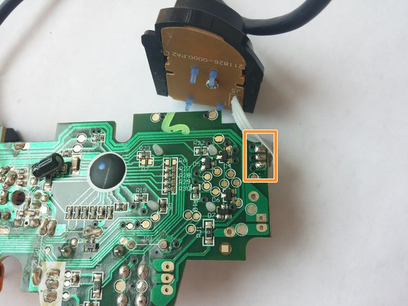
The 3 wires are soldered into the 3 spots circled on the picture.
-


Отменить: Я не выполнил это руководство.
4 участников успешно повторили данное руководство.
Команда

USF Tampa, Team 7-4, Remmell Winter 2015 Участник USF Tampa, Team 7-4, Remmell Winter 2015
USFT-REMMELL-W15S7G4
4 членов
Автор 3 руководств