Эта версия возможно содержит некорректные исправления. Переключить на последнюю проверенную версию.
Выберете то, что вам нужно
-
Этот шаг не переведен. Помогите перевести
-
Remove the 2.6 mm T6 screw securing the SATA cable connector bracket.
-
-
Этот шаг не переведен. Помогите перевести
-
Use the flat end of a spudger to lift the SATA cable connector up off of its socket on the logic board.
-
-
Этот шаг не переведен. Помогите перевести
-
Use the tip of a spudger to disconnect the IR sensor cable connector by prying it straight up from its socket.
-
-
-
Этот шаг не переведен. Помогите перевести
-
The following three steps only apply to Mac minis equipped with a PCIe SSD. Skip the next three steps if your Mac mini only has a hard drive.
-
Remove the two 2.6 mm T6 screws securing the PCIe SSD cable bracket.
-
-
Этот шаг не переведен. Помогите перевести
-
Remove the single 16 mm T6 screw securing the logic board.
-
-
Этот шаг не переведен. Помогите перевести
-
Insert the Mac mini Logic Board Removal Tool into the two holes highlighted in red. Be sure the rods make contact with the case under the logic board before proceeding.
-
-
Этот шаг не переведен. Помогите перевести
-
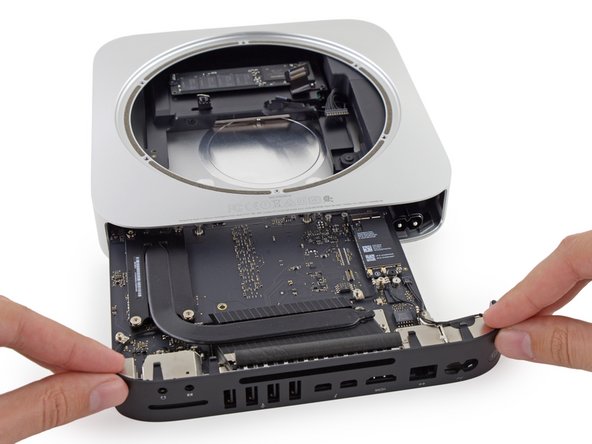
Carefully pull the tool toward the I/O board. The logic board and I/O board assembly should slightly slide out of the outer case.
-
Cease prying when the removal tool makes contact with the opening in the rear case.
-
-
Этот шаг не переведен. Помогите перевести
-
Pull the DC-In cable connector straight out of its socket on the logic board.
-
-
Этот шаг не переведен. Помогите перевести
-
Carefully slide the logic board assembly out of the Mac mini, minding any cables that may get caught.
-


Отменить: Я не выполнил это руководство.
Еще один человек закончил это руководство.

