Эта версия возможно содержит некорректные исправления. Переключить на последнюю проверенную версию.
Выберете то, что вам нужно
-
Этот шаг не переведен. Помогите перевести
-
Slide the lock switch to the right, to the unlocked position.
-
-
Этот шаг не переведен. Помогите перевести
-
Remove five 5.1 mm T10 Torx screws from around the outer perimeter of the fan assembly.
-
-
Этот шаг не переведен. Помогите перевести
-
While supporting the fan assembly with one hand, loosen the two T8 captive screws in the fan cable bracket.
-
-
Этот шаг не переведен. Помогите перевести
-
Use a pair of tweezers to pull the fan cable bracket away from the fan assembly.
-
-
Этот шаг не переведен. Помогите перевести
-
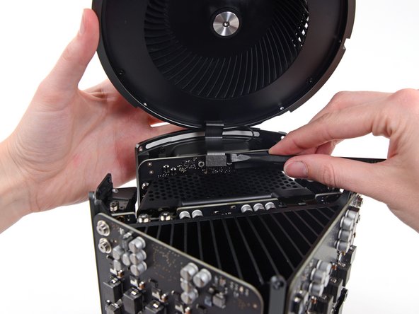
Use the flat end of a spudger to disconnect the fan assembly ribbon cable from the IO board.
-
-
Этот шаг не переведен. Помогите перевести
-
Disconnect the fan assembly antenna cable from the IO board.
-
Remove the fan assembly from the Mac Pro.
-
-
Этот шаг не переведен. Помогите перевести
-
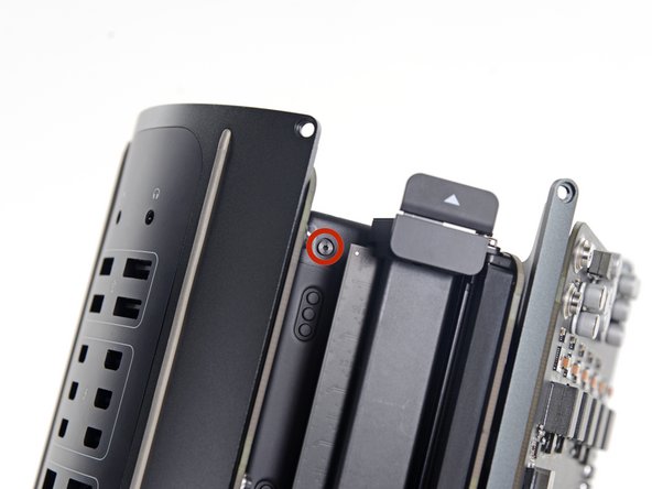
Remove five 5.1 mm T10 Torx screws from the outer perimeter of the lower case.
-
-
Этот шаг не переведен. Помогите перевести
-
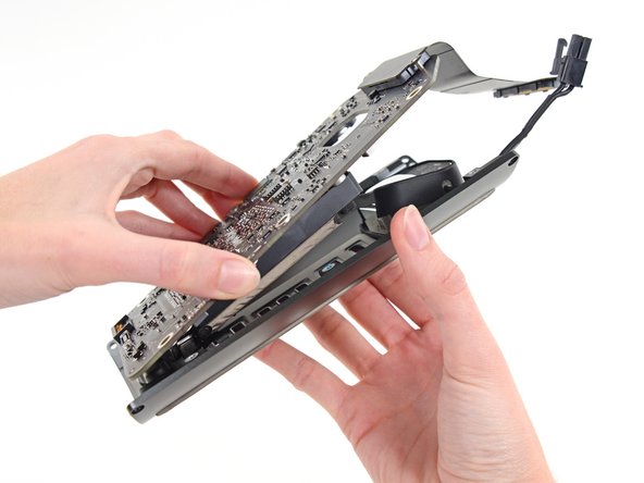
Carefully lift the lower case up and remove it from the Mac Pro.
-
-
Этот шаг не переведен. Помогите перевести
-
Use the flat end of a spudger and a twisting motion to gently separate one side of the graphics card data connection.
-
-
-
Этот шаг не переведен. Помогите перевести
-
Gently separate the other side as well.
-
Flip the connector up and out of the way of the graphics card.
-
-
Этот шаг не переведен. Помогите перевести
-
Remove the two 6.0 mm T8 Torx screws securing the interconnect board to the heat sink.
-
-
Этот шаг не переведен. Помогите перевести
-
Gently walk the interconnect board straight up off the logic board's slot connection.
-
-
Этот шаг не переведен. Помогите перевести
-
Flip the interconnect board up and over, exposing the IO board data cable.
-
Use the same sort of twisting and spreading motion with the flat end of a spudger to separate one side of the IO board data cable.
-
-
Этот шаг не переведен. Помогите перевести
-
Use the flat end of a spudger to separate the other side of the IO board data cable.
-
Bend the cable out of the way and remove the interconnect board from the Mac Pro.
-
-
Этот шаг не переведен. Помогите перевести
-
Flip the Mac Pro back over and set it gently on a flat surface.
-
-
Этот шаг не переведен. Помогите перевести
-
Remove the two 3.6 mm T5 Torx screws from the sides of the power supply cage (one on each side).
-
-
Этот шаг не переведен. Помогите перевести
-
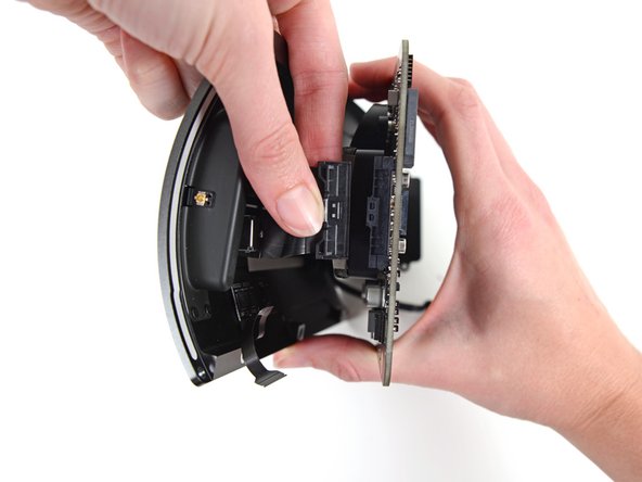
Remove the power supply cage from the top of the power supply.
-
-
Этот шаг не переведен. Помогите перевести
-
Remove the four 5.5 mm T8 Torx screws securing the power supply assembly to the Mac Pro.
-
-
Этот шаг не переведен. Помогите перевести
-
Use the flat end of a spudger to disconnect the power supply DC-Out connector from its socket on the IO board.
-
Use the tip of a spudger to disconnect the power supply data cable from its socket on the IO board.
-
-
Этот шаг не переведен. Помогите перевести
-
Remove the four 9.0 mm silver T10 Torx screws from the sides of the power supply.
-
-
Этот шаг не переведен. Помогите перевести
-
Gently shift the power supply to free the AC power inlet cable out of its plastic clip.
-
-
Этот шаг не переведен. Помогите перевести
-
Flip the power supply back to expose the AC power inlet cable.
-
-
Этот шаг не переведен. Помогите перевести
-
Squeeze the AC power inlet cable connector and pull it straight out of its socket in the power supply.
-
-
Этот шаг не переведен. Помогите перевести
-
Remove the two 9 mm silver T10 Torx screws securing the IO Board to the IO shield.
-
-
Этот шаг не переведен. Помогите перевести
-
Lift the IO board up from the IO shield from the end with the AC plug.
-
-
Этот шаг не переведен. Помогите перевести
-
Use the tip of a spudger to flip the retaining flap on the IO shield ribbon cable ZIF connector.
-
Disconnect the IO shield ribbon cable.
-
-
Этот шаг не переведен. Помогите перевести
-
Squeeze and pull the audio jack ribbon cable connector from the IO board.
-
-
Этот шаг не переведен. Помогите перевести
-
Remove the four 6.5 mm T4 screws (with washers) from the flange around the AC socket.
-


Отменить: Я не выполнил это руководство.
4 участников успешно повторили данное руководство.

Один комментарий
Does anyone know where to purchase the screw sets for the Mac Pro?