Эта версия возможно содержит некорректные исправления. Переключить на последнюю проверенную версию.
Выберете то, что вам нужно
-
Этот шаг не переведен. Помогите перевести
-
Use the flat end of a spudger to pry both antenna connectors up from their sockets on the AirPort/Bluetooth card, and move them out of the way.
-
-
Этот шаг не переведен. Помогите перевести
-
Remove the following five screws securing the battery to the upper case:
-
Two 5.2 mm T5 Torx screws
-
One 6 mm T5 Torx screw
-
Two 2.6 mm T5 Torx screws
-
-
Этот шаг не переведен. Помогите перевести
-
Lift the battery from its edge nearest the logic board and remove it from the upper case.
-
-
Этот шаг не переведен. Помогите перевести
-
Disconnect the I/O board by pulling the power cable away from its socket on the logic board.
-
-
Этот шаг не переведен. Помогите перевести
-
Use the tip of a spudger to de-route the antenna cables from their notches in the logic board.
-
-
-
Этот шаг не переведен. Помогите перевести
-
Gently push the tip of a spudger under the black plastic flap stuck to the display data cable lock to make the lock pop upward and away from the socket.
-
While holding the lock away from the socket, gently pull the display data cable out of its socket.
-
-
Этот шаг не переведен. Помогите перевести
-
Use the tip of a spudger to pry under the speaker cable connector, lifting it straight up from its socket.
-
De-route the cable from its notch in the logic board.
-
-
Этот шаг не переведен. Помогите перевести
-
Use the tip of a spudger or your fingernail to flip up the retaining flap on the trackpad ribbon cable ZIF socket.
-
Pull the trackpad ribbon cable straight out of its socket toward the front edge of the Air.
-
-
Этот шаг не переведен. Помогите перевести
-
Use the tip of a spudger to flip up the retaining flap on the keyboard backlight ribbon cable ZIF socket.
-
Pull the keyboard backlight ribbon cable out of its socket.
-
-
Этот шаг не переведен. Помогите перевести
-
Remove the single 2.9 mm T5 Torx screw securing the AirPort/Bluetooth card to the logic board.
-
-
Этот шаг не переведен. Помогите перевести
-
Slightly lift the free end of the AirPort/Bluetooth board and pull it out of its socket on the logic board.
-
-
Этот шаг не переведен. Помогите перевести
-
Remove the three 3.6 mm T5 Torx screws securing the logic board to the upper case.
-
In some models these are 3.1 mm T5 Torx screws.
-
-
Этот шаг не переведен. Помогите перевести
-
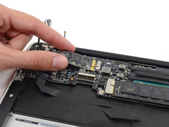
Gently lift the logic board assembly from the heat sink end and pull it away from the port side of the case to remove it from the Air.
-


Отменить: Я не выполнил это руководство.
Еще один человек закончил это руководство.

