Эта версия возможно содержит некорректные исправления. Переключить на последнюю проверенную версию.
Выберете то, что вам нужно
-
Этот шаг не переведен. Помогите перевести
-
Use the tip of a spudger or your fingernail to flip up the retaining flap on the trackpad ribbon cable ZIF socket.
-
Pull the trackpad ribbon cable straight out of its socket toward the front edge of the Air.
-
-
Этот шаг не переведен. Помогите перевести
-
Use the flat end of a spudger to pry the right speaker cable connector up and out of its socket on the logic board.
-
-
Этот шаг не переведен. Помогите перевести
-
Gently push the tip of a spudger under the black plastic flap stuck to the display data cable lock to make the lock pop upward and away from the socket.
-
While holding the lock away from the socket, use the tip of a spudger and your fingers to gently remove the display data cable from its socket by sliding it toward the corner of the Air.
-
-
Этот шаг не переведен. Помогите перевести
-
Use the flat end of a spudger to pry both antenna cable connectors up and off their sockets on the AirPort/Bluetooth card.
-
-
-
Этот шаг не переведен. Помогите перевести
-
Gently de-route the antenna cables from the slot cut into the logic board.
-
-
Этот шаг не переведен. Помогите перевести
-
Remove the single 2.85 mm T5 Torx screw securing the SSD to the logic board.
-
-
Этот шаг не переведен. Помогите перевести
-
Pull the drive straight out of its socket and remove it from the logic board.
-
-
Этот шаг не переведен. Помогите перевести
-
Remove the six 6.3 mm T5 Torx screws securing the logic board to the upper case.
-
-
Этот шаг не переведен. Помогите перевести
-
Remove the inner two 4.9 mm T8 Torx screws securing the antenna cable retainer and left clutch hinge to the upper case.
-
-
Этот шаг не переведен. Помогите перевести
-
Push the antenna cable retainer away slightly and remove the 3 mm T5 Torx screw securing the end of the heat sink to the upper case.
-
-
Этот шаг не переведен. Помогите перевести
-
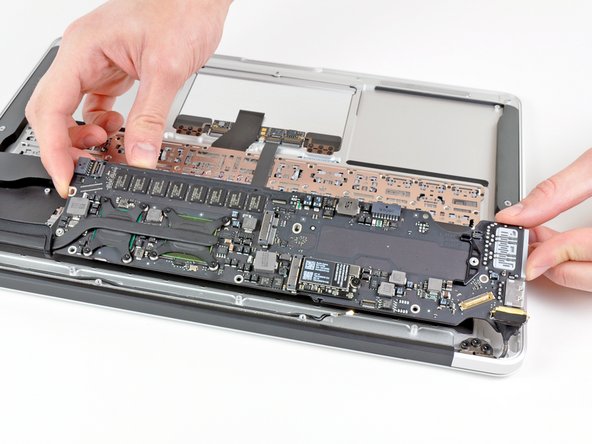
Carefully remove the logic board assembly from the upper case, minding any cables that may get caught.
-