Эта версия возможно содержит некорректные исправления. Переключить на последнюю проверенную версию.
Выберете то, что вам нужно
-
Этот шаг не переведен. Помогите перевести
-
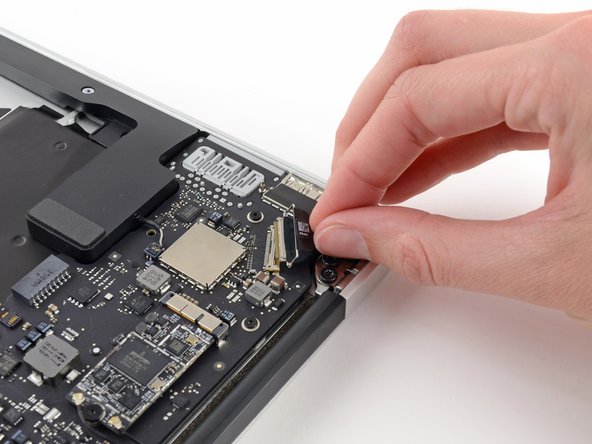
Grab the plastic pull tab secured to the display data cable lock and rotate it towards the top side of the computer.
-
-
Этот шаг не переведен. Помогите перевести
-
Pull the display data cable connector straight away from its socket.
-
-
Этот шаг не переведен. Помогите перевести
-
Use the flat end of a spudger to pry both antenna cable connectors up and off their sockets on the AirPort/Bluetooth card.
-
-
Этот шаг не переведен. Помогите перевести
-
Disconnect the camera cable connector with the tip of a spudger.
-
Pull the camera cable parallel to the face of the I/O board toward the front edge of the Air to disconnect it from its socket.
-
-
-
Этот шаг не переведен. Помогите перевести
-
Use the tip of a spudger or your fingernail to flip up the retaining flap on the trackpad ribbon cable ZIF socket.
-
Pull the trackpad ribbon cable straight out of its socket toward the front edge of the Air.
-
-
Этот шаг не переведен. Помогите перевести
-
Use the tip of a spudger to flip up the retaining flap on the keyboard backlight ribbon cable ZIF socket.
-
Use your spudger to gently pull the keyboard backlight ribbon cable out of its socket.
-
-
Этот шаг не переведен. Помогите перевести
-
Use the flat end of a spudger to pry the right speaker cable connector up and out of its socket on the logic board.
-
-
Этот шаг не переведен. Помогите перевести
-
Remove the six 6.3 mm T5 Torx screws securing the logic board to the upper case.
-
-
Этот шаг не переведен. Помогите перевести
-
Remove the inner two 4.9 mm T8 Torx screws securing the antenna cable retainer and left clutch hinge to the upper case.
-
-
Этот шаг не переведен. Помогите перевести
-
Push the antenna cable retainer away slightly and remove the 3 mm T5 Torx screw securing the end of the heat sink to the upper case.
-
-
Этот шаг не переведен. Помогите перевести
-
Slide the flat end of a spudger under the right speaker from the end nearest the hinge to the front edge of the Air to loosen the adhesive.
-
Remove the right speaker from the upper case.
-
-
Этот шаг не переведен. Помогите перевести
-
Carefully remove the logic board assembly from the upper case, minding any cables that may get caught.
-
Keep loose cables clear of the board so they aren't caught under it.
-
Make sure the antenna cables are inserted into their respective notches, as highlighted in the second picture.
-


Отменить: Я не выполнил это руководство.
Еще один человек закончил это руководство.
