Введение
Use this guide to replace the upper case.
Выберете то, что вам нужно
-
Инструмент, используемый на этом этапе:P5 Pentalobe Screwdriver Retina MacBook Pro and Air$5.99
-
Use a P5 Pentalobe driver to remove ten screws securing the lower case, of the following lengths:
-
Two 9 mm screws
-
Eight 2.6 mm screws
-
-
-
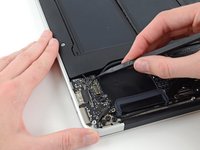
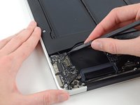
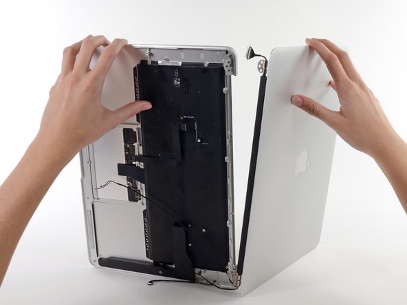
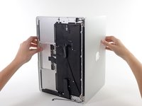
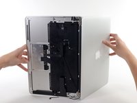
Wedge your fingers between the display and the lower case and pull upward to pop the lower case off the Air.
-
Remove the lower case and set it aside.
-
-
-
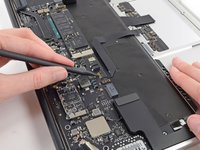
Grab the clear plastic pull tab attached to the battery connector and pull it parallel to the board toward the front edge of the Air.
-
-
-
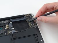
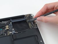
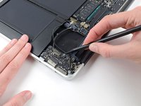
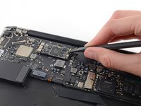
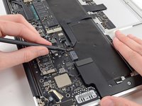
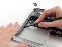
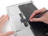
Use the flat end of a spudger to pry the I/O board cable connector up out of its socket on the I/O board.
-
-
-
Carefully peel the I/O board cable from the adhesive securing it to the top of the fan.
-
-
-
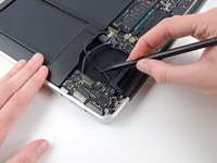
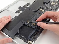
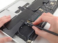
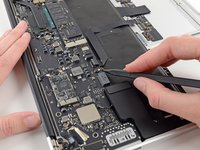
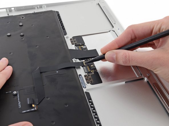
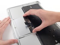
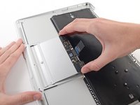
While gently pulling the I/O board cable upward near its connection to the logic board, use the flat end of a spudger to pry up on alternating sides of the connector to help "walk" it out of its socket.
-
Remove the I/O board cable.
-
-
-
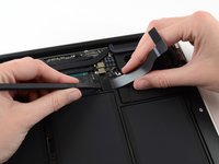
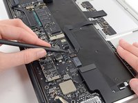
Use the tip of a spudger to carefully flip up the retaining flap on the fan cable ZIF socket.
-
-
-
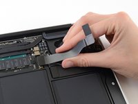
Remove the following three screws securing the fan to the upper case:
-
One 3.6 mm T5 Torx screw
-
One 2.7 mm T5 Torx screw
-
One 3.6 mm T5 Torx screw with a short head
-
-
-
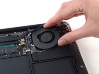
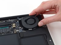
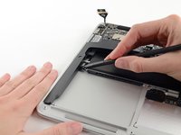
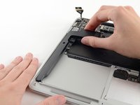
Lift the fan from the I/O board side and pull it free from the upper case.
-
Removing the fan will also disconnect the fan ribbon cable. Be careful not to snag it.
-
-
-
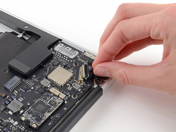
Disconnect the I/O board by pulling its power cable away from its socket on the logic board.
-
-
-
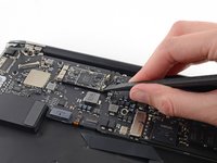
Use the flat end of a spudger to pry the left speaker cable connector up and out of its socket on the I/O board.
-
-
-
Use the tip of a spudger to carefully flip up the retaining flap on the microphone ribbon cable ZIF socket.
-
-
-
Remove the single 3.6 mm T5 Torx screw securing the I/O board to the upper case.
-
-
-
-
Gently de-route the camera cable from its notch on the I/O board and push it out of the way with the tip of a spudger.
-
-
-
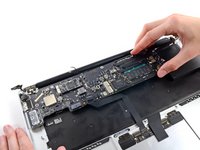
Lift the I/O board from the logic board side and pull it free from the upper case.
-
Removing the I/O board will also disconnect the microphone ribbon cable. Be careful not to snag it.
-
-
-
Remove the following five screws securing the battery to the upper case:
-
Three 6.3 mm T5 Torx screws
-
Two 2.4 mm T5 Torx screws
-
-
-
Lift the battery from its edge nearest the logic board and remove it from the upper case.
-
-
-
Grab the plastic pull tab secured to the display data cable lock and rotate it towards the top side of the computer.
-
-
-
Use the flat end of a spudger to pry both antenna cable connectors up and off their sockets on the AirPort/Bluetooth card.
-
-
-
Disconnect the camera cable connector with the tip of a spudger.
-
Pull the camera cable parallel to the face of the I/O board toward the front edge of the Air to disconnect it from its socket.
-
-
-
Use the tip of a spudger or your fingernail to flip up the retaining flap on the trackpad ribbon cable ZIF socket.
-
Pull the trackpad ribbon cable straight out of its socket toward the front edge of the Air.
-
-
-
Use the tip of a spudger to flip up the retaining flap on the keyboard backlight ribbon cable ZIF socket.
-
Use your spudger to gently pull the keyboard backlight ribbon cable out of its socket.
-
-
-
Use the flat end of a spudger to pry the right speaker cable connector up and out of its socket on the logic board.
-
-
-
Remove the six 6.3 mm T5 Torx screws securing the logic board to the upper case.
-
-
-
Remove the inner two 4.9 mm T8 Torx screws securing the antenna cable retainer and left clutch hinge to the upper case.
-
-
-
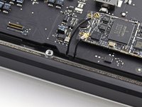
Push the antenna cable retainer away slightly and remove the 3 mm T5 Torx screw securing the end of the heat sink to the upper case.
-
-
-
Slide the flat end of a spudger under the right speaker from the end nearest the hinge to the front edge of the Air to loosen the adhesive.
-
Remove the right speaker from the upper case.
-
-
-
Carefully remove the logic board assembly from the upper case, minding any cables that may get caught.
-
Keep loose cables clear of the board so they aren't caught under it.
-
Make sure the antenna cables are inserted into their respective notches, as highlighted in the second picture.
-
-
-
Remove the inner two 4.9 mm T8 Torx screws securing the right display hinge to the upper case.
-
-
-
While holding the Air steady, remove the remaining 4.9 mm T8 Torx screw from the display bracket.
-
-
-
Open the Air slowly until the hinges slide out of their notches.
-
Once the two display hinges have cleared the upper case, remove the display and set it aside.
-
-
-
Use the flat end of a spudger to pry the left speaker off the adhesive securing it to the upper case.
-
Remove the left speaker from the upper case.
-
-
-
Use the flat end of a spudger to pry the microphone off the adhesive securing it to the left side of the upper case.
-
If needed, apply a little heat from an iOpener or hairdryer to soften the adhesive.
-
Remove the microphone from the upper case.
-
-
-
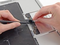
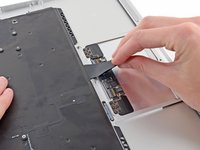
Use the tip of a spudger or your fingernail to flip up the retaining flap on the trackpad ribbon cable ZIF socket.
-
Pull the trackpad ribbon cable straight out of its socket toward the rear edge of the Air.
-
-
-
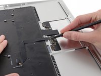
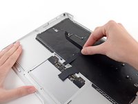
While carefully lifting the keyboard ribbon cable with one hand, use the tip of a spudger or your fingernail to flip up the retaining flap on the keyboard ribbon cable ZIF socket.
-
Pull the keyboard ribbon cable straight out of its socket toward the front edge of the Air.
-
-
-
Remove the following seven screws:
-
Six 1.6 mm Phillips screws securing the trackpad to the upper case.
-
One 1.4 mm T5 Torx set screw from its tapped hole near the front edge of the upper case.
-
-
-
Carefully lift the edge of the trackpad closest to the keyboard from its recess in the upper case by lifting it away from the brackets attached to the upper case.
-
Remove the trackpad from the upper case.
-
The upper case remains.
-


To reassemble your device, follow these instructions in reverse order.
Отменить: Я не выполнил это руководство.
56 человек успешно провели ремонт по этому руководству.

9 Комментарии к руководству
Hello all,
Could someone confirm if a upper case with keyboard from A1466 mid 2012 will fit well in A1466 mid 2013?
Thanks!
Wondering the same thing here, any luck?
Very helpful. Step 29 seems to duplicate step 17.
Step 29 is taking out the speakers. Step 17 is taking out the battery.
mel -
what type of adhesive do you need to reattach all of the stuff that was pried off? Or do you not need one?