Введение
No power to the laptop? Replace the MagSafe board.
Выберете то, что вам нужно
-
-
Use a coin or spudger to rotate the battery-locking screw 90 degrees clockwise.
-
-
-
Unscrew the three evenly-spaced Phillips 000 screws from along the rear wall of the battery compartment.
-
-
-
Grasp the right end of the L-shaped memory cover, then pull it towards you so it clears the battery compartment opening.
-
Lift the memory cover up and out of the computer.
-
-
-
Remove the following 3 screws:
-
One 11 mm Phillips#00 in the middle of the lower case. (Head: 5mm dia. x .75mm thick)
-
Two 14.5 mm Phillips #00 (Head: 5mm dia. x .75mm thick)
-
-
-
Remove the following 3 screws from the rear wall of the battery compartment:
-
One 3 mm Phillips #0. (Head: 2.75 mm. dia.)
-
Two 4 mm Phillips #0 on the either side. (Head: 2.75mm dia.)
-
-
-
-
Remove the two Phillips screws from either side of the right wall of the battery compartment (not the ones closest to the battery connector).
-
Two 6.25 mm Phillips #000. (Head: 4 mm. dia. x .5mm thick)
-
-
-
Remove the four indicated Phillips screws from the front wall of the battery compartment. When working from the left, remove the 2nd, 4th, 7th and 9th screws.
-
Four 3.25 mm Phillips #000. (Head: 4 mm. dia. x 4mm thick)
-
-
-
Remove the following 4 screws from the back of the computer:
-
Two 11 mm Phillips #00, with Shank (2.2mm dia. x 2 mm len.) (Head: 3.2 mm. dia. x .5mm thick)
-
Two 7.25 mm Phillips #00, with Shank (2mm dia. x 3.75 mm len.) (Head: 3.2 mm. dia. x .5mm thick)
-
-
-
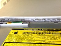
Remove the two Phillips screws from the optical drive (right) side of the computer:
-
Two 5.2 mm Phillips #00, with shank (2.3mm dia. x 3.25 mm len.) (Head: 3.2 mm. dia. x .5mm thick)
-
-
Инструмент, используемый на этом этапе:Plastic Cards$2.99
-
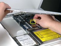
Use a plastic opening tool, an expired plastic credit, or a similarly-thick card to pry up on the upper case, starting in the upper-left corner and working around to the front of the computer.
-
-
-
While holding up the upper case, pull up the black tab on the connector end of the silver ribbon cable away from the connector's socket on the logic board.
-
-
-
Remove the left 3 mm and right 8 mm (right screw is unnecessary to remove on some models)
-
One 3.25mm Phillips #000 (Head: 4mm dia. x .5mm thick)
-
One 8.5mm Phillips #000 (Head: 4mm dia. x .75mm thick
-
-
-
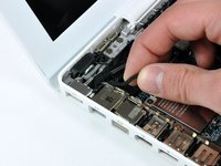
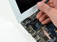
Gently de-route the speaker cable from the left I/O frame.
-
Use a spudger to lift the left speaker out of its housing. Grasp it with your fingers and move it out of the way.
-
-
-
Remove the following three screws securing the left I/O frame:
-
Two 7.5 mm Phillips screws from the top and bottom end of the left I/O frame.
-
One 9 mm Phillips from the middle of the left I/O frame.
-
On some models, all three screws may be the same size.
-
-
-
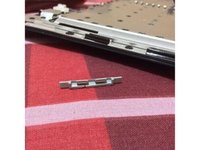
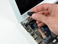
The MagSafe board is now free of all connections and can be detached freely from the logic board.
-
Using your fingers, pull out the MagSafe board.
-


To reassemble your device, follow these instructions in reverse order.
Отменить: Я не выполнил это руководство.
137 человек успешно провели ремонт по этому руководству.

4 Комментарии к руководству
Since the use of magnetic tipped drivers is probably NOT recommended, I'd keep some partially dried rubber cement or similar (snotty consistency) around to stick screws onto the driver tips. It makes guiding the screw into cramped areas much easier and rubs right off afterwards.
I believe every single screw that I unscrewed required a Phillips #000 (instead of #0 or #00). Could just be my model. Great guide otherwise.
Following this guide, I fixed the balanced audio on my laptop. I appreciate your thorough instruction. My goal is to open a repair shop, but in order to do that, I must learn a lot from you. gartic phone
Bahçeşehir Konut Projeleri thanks for helpfull writing. this article very important and true.