Введение
Use this guide to replace the I/O board data cable.
Выберете то, что вам нужно
-
Инструмент, используемый на этом этапе:Magnetic Project Mat$19.95
-
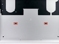
Remove the following ten screws securing the lower case to the upper case:
-
Two 2.3 mm P5 Pentalobe screws
-
Eight 3.0 mm P5 Pentalobe screws
-
-
-
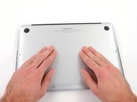
Wedge your fingers between the upper case and the lower case.
-
Gently pull the lower case away from the upper case.
-
Remove the lower case and set it aside.
-
-
-
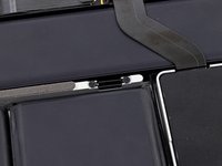
The lower case is connected to the upper case at the center, with two plastic clips.
-
-
-
Remove the plastic cover adhered to the battery contact board.
-
-
-
-
Remove the following screws securing the battery connector board to the logic board:
-
Two 2.8 mm T6 Torx screws
-
One 7.0 mm T6 Torx shouldered screw
-
-
Инструмент, используемый на этом этапе:Tweezers$4.99
-
Use tweezers to remove the small plastic cover located near the bottom right of the battery connector board.
-
-
-
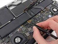
Remove the wide head 6.4 mm T6 Torx screw securing the battery connector to the logic board assembly.
-
-
-
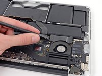
Carefully lift the battery connector board up off the logic board.
-
It is recommended to bend the battery cables just slightly, to keep the board suspended up above the logic board and out of the way.
-
-
Инструмент, используемый на этом этапе:Tweezers$4.99
-
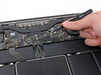
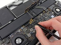
Grasp the Interposer with tweezers.
-
Lift the Interposer off the logic board and remove it.
-
-
-
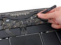
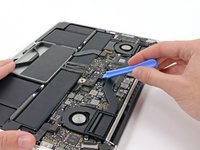
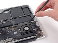
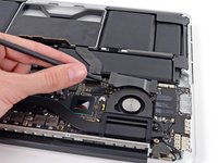
Use the flat end of a spudger to pry the right side of the I/O board data cable connector up off its socket on the I/O board.
-
-
-
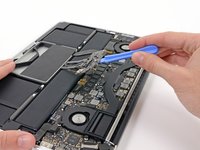
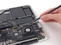
Wedge the flat end of a spudger beneath the left side of the I/O board data cable connector.
-
Gently twist the spudger to disconnect the I/O board data cable connector from its socket on the logic board.
-


To reassemble your device, follow these instructions in reverse order.
To reassemble your device, follow these instructions in reverse order.
Отменить: Я не выполнил это руководство.
4 человек успешно провели ремонт по этому руководству.
