Перейти к основному содержанию

MacBook Pro 13" Retina Display Late 2012 Logic Board Assembly Replacement

Абсолютно необходимое руководство
Это руководство предназначено только для использования в качестве обязательного условия для других руководств. Оно не полностью само по себе.

Выберете то, что вам нужно

  1. MacBook Pro 13" Retina Display Late 2012 Logic Board Assembly Replacement, Logic Board Assembly: шаг 1, изображение 1 из 2 MacBook Pro 13" Retina Display Late 2012 Logic Board Assembly Replacement, Logic Board Assembly: шаг 1, изображение 2 из 2
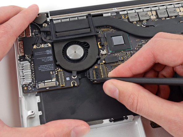
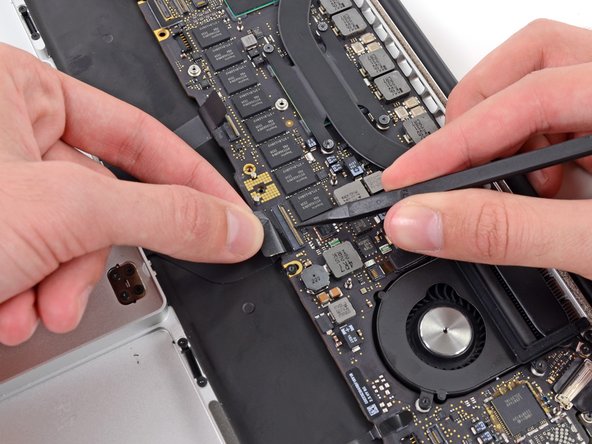
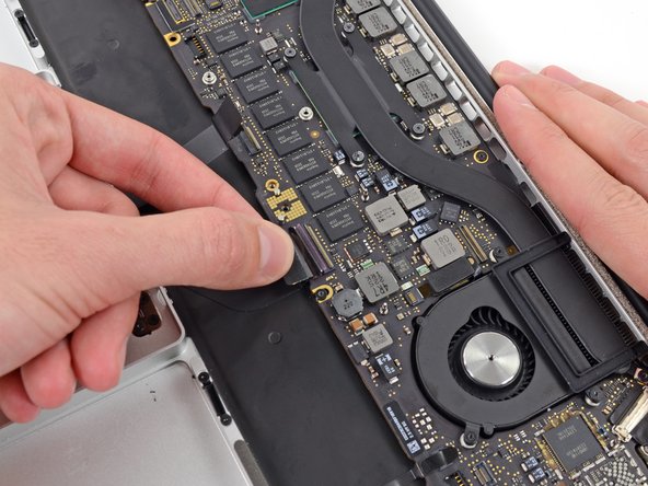
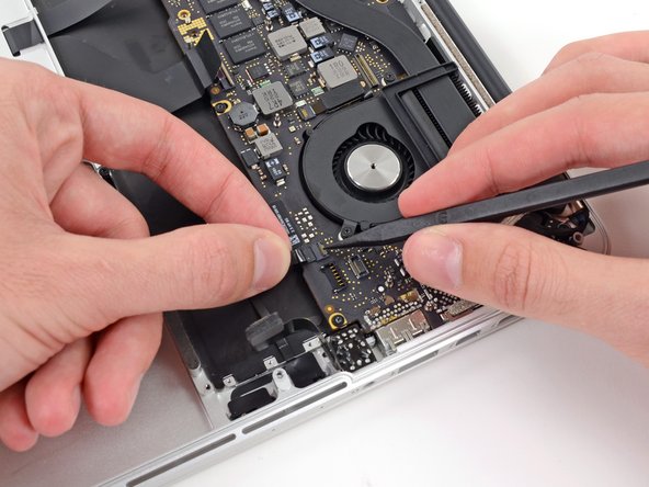
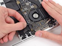
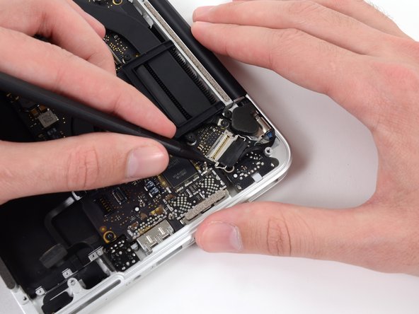
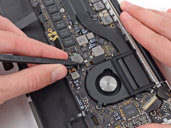
    • Use the tip of a spudger to push the edges of the I/O board connector straight out of its socket on the logic board.

    • It is recommended to carefully push on both sides of the connector to "walk" it out of its socket.

  2. MacBook Pro 13" Retina Display Late 2012 Logic Board Assembly Replacement: шаг 2, изображение 1 из 2 MacBook Pro 13" Retina Display Late 2012 Logic Board Assembly Replacement: шаг 2, изображение 2 из 2
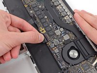
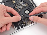
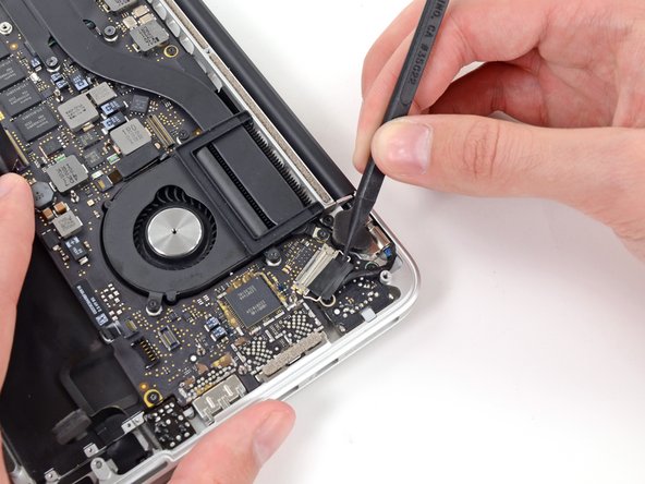
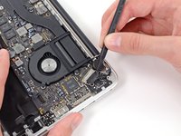
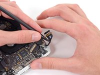
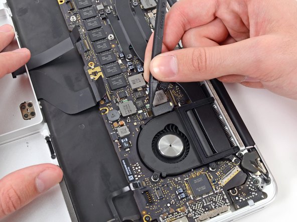
    • Use the tip of a spudger to push the iSight camera cable connector straight away from its socket on the logic board.

    • It is recommended to carefully push on both sides of the connector to "walk" it out of its socket.

  3. MacBook Pro 13" Retina Display Late 2012 Logic Board Assembly Replacement: шаг 3, изображение 1 из 2 MacBook Pro 13" Retina Display Late 2012 Logic Board Assembly Replacement: шаг 3, изображение 2 из 2
    • Move the iSight camera cable aside.

  4. MacBook Pro 13" Retina Display Late 2012 Logic Board Assembly Replacement: шаг 4, изображение 1 из 2 MacBook Pro 13" Retina Display Late 2012 Logic Board Assembly Replacement: шаг 4, изображение 2 из 2
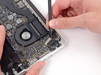
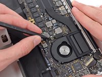
    • Wedge the flat end of a spudger underneath the keyboard backlight connector and the logic board.

    • Gently twist the flat end of a spudger upwards to pry the keyboard backlight connector up off its socket on the logic board.

  5. MacBook Pro 13" Retina Display Late 2012 Logic Board Assembly Replacement: шаг 5, изображение 1 из 2 MacBook Pro 13" Retina Display Late 2012 Logic Board Assembly Replacement: шаг 5, изображение 2 из 2
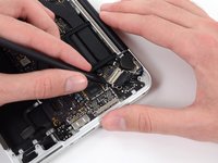
    • Use the tip of a spudger to flip up the retaining flap on the trackpad ribbon cable ZIF socket.

    • Be sure you are prying up on the hinged retaining flap, not the socket itself.

    • Grasp the plastic pull tab and pull the trackpad ribbon cable out of its socket.

  6. MacBook Pro 13" Retina Display Late 2012 Logic Board Assembly Replacement: шаг 6, изображение 1 из 3 MacBook Pro 13" Retina Display Late 2012 Logic Board Assembly Replacement: шаг 6, изображение 2 из 3 MacBook Pro 13" Retina Display Late 2012 Logic Board Assembly Replacement: шаг 6, изображение 3 из 3
    • Use the tip of a spudger to flip up the retaining flap on the keyboard ribbon cable ZIF socket.

    • Be sure you are prying up on the hinged retaining flap, not the socket itself.

    • Grasp the plastic pull tab and pull the keyboard ribbon cable out of its socket.

  7. MacBook Pro 13" Retina Display Late 2012 Logic Board Assembly Replacement: шаг 7, изображение 1 из 3 MacBook Pro 13" Retina Display Late 2012 Logic Board Assembly Replacement: шаг 7, изображение 2 из 3 MacBook Pro 13" Retina Display Late 2012 Logic Board Assembly Replacement: шаг 7, изображение 3 из 3
    • Use the tip of a spudger to flip up the retaining flap on the microphone ribbon cable ZIF socket.

    • Be sure you are prying up on the hinged retaining flap, not the socket itself.

    • Grasp the plastic pull tab and pull the microphone ribbon cable out of its socket.

  8. MacBook Pro 13" Retina Display Late 2012 Logic Board Assembly Replacement: шаг 8, изображение 1 из 2 MacBook Pro 13" Retina Display Late 2012 Logic Board Assembly Replacement: шаг 8, изображение 2 из 2
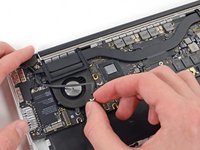
    • Use the tip of a spudger to rotate the pull tab secured to the display data cable lock toward the DC-In side of the computer.

  9. MacBook Pro 13" Retina Display Late 2012 Logic Board Assembly Replacement: шаг 9, изображение 1 из 3 MacBook Pro 13" Retina Display Late 2012 Logic Board Assembly Replacement: шаг 9, изображение 2 из 3 MacBook Pro 13" Retina Display Late 2012 Logic Board Assembly Replacement: шаг 9, изображение 3 из 3
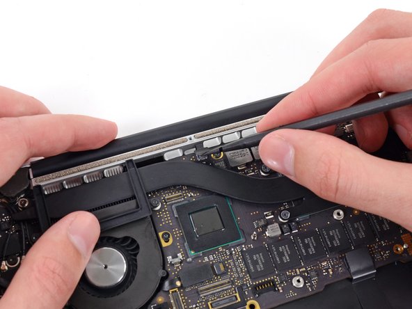
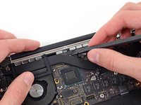
    • Gently push the edges of the display data cable connector away from its socket on the logic board.

    • It is recommended "walk" the connector out of its socket. Simply push the top and bottom corners of the connector and carefully "walk it out" of its socket.

    • Pull, but do not remove, the display data cable connector out of its socket and carefully move it out of the way.

  10. MacBook Pro 13" Retina Display Late 2012 Logic Board Assembly Replacement: шаг 10, изображение 1 из 3 MacBook Pro 13" Retina Display Late 2012 Logic Board Assembly Replacement: шаг 10, изображение 2 из 3 MacBook Pro 13" Retina Display Late 2012 Logic Board Assembly Replacement: шаг 10, изображение 3 из 3
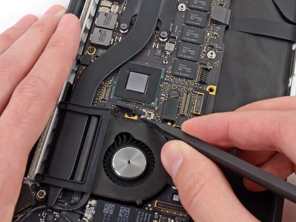
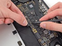
    • Use the tip of a spudger to flip up the retaining flap on the left fan ribbon cable ZIF socket.

    • Be sure you are prying up on the hinged retaining flap, not the socket itself.

    • Carefully pull the left fan ribbon cable out of its socket.

  11. MacBook Pro 13" Retina Display Late 2012 Logic Board Assembly Replacement: шаг 11, изображение 1 из 1
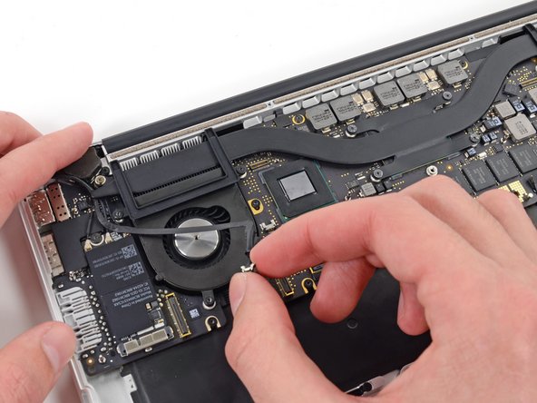
    • Move the left fan ribbon cable aside to reveal a hidden screw securing the logic board assembly to the upper case.

  12. MacBook Pro 13" Retina Display Late 2012 Logic Board Assembly Replacement: шаг 12, изображение 1 из 2 MacBook Pro 13" Retina Display Late 2012 Logic Board Assembly Replacement: шаг 12, изображение 2 из 2
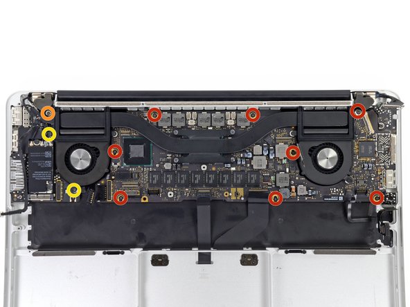
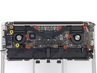
    • Remove the following screws securing the logic board to the upper case:

    • Eight 3.3 mm T5 Torx screws

    • One Phillips #00 screw

    • Two 3.1 mm T5 Torx screws

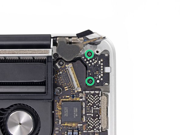
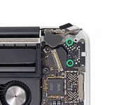
    • Remove two more screws, from the MagSafe DC-In board in the upper right corner (second image).

    • Two 3.4 mm T5 Torx screws

  13. MacBook Pro 13" Retina Display Late 2012 Logic Board Assembly Replacement: шаг 13, изображение 1 из 2 MacBook Pro 13" Retina Display Late 2012 Logic Board Assembly Replacement: шаг 13, изображение 2 из 2
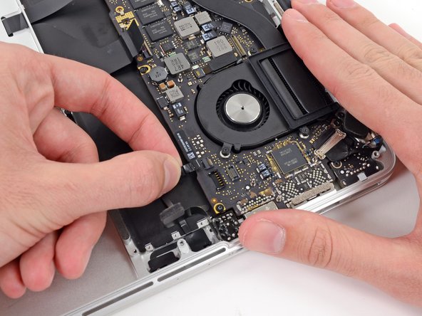
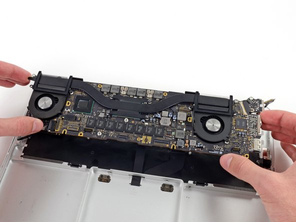
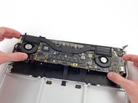
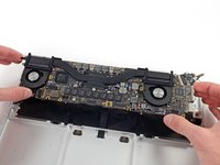
    • Carefully lift the logic board assembly from its left side and work it out of the upper case, minding any cables and the I/O ports that may get caught during removal.

    • Pull the right I/O port side of the logic board away from the side of the upper case and remove the logic board assembly.

Заключение

To reassemble your device, follow these instructions in reverse order.

0 Комментариев

Добавить комментарий

Просмотр статистики:

За последние 24часов: 0

За последние 7 дней: 0

За последние 30 дней: 0

За всё время: 100