Перейти к основному содержанию

Эта версия возможно содержит некорректные исправления. Переключить на последнюю проверенную версию.

Выберете то, что вам нужно

  1. Этот шаг не переведен. Помогите перевести

    : шаг 1, изображение 1 из 1
    Инструмент, используемый на этом этапе:
    Magnetic Project Mat
    $19.95
    Купить
    • Remove the following ten screws securing the lower case to the upper case:

    • Two 2.3 mm P5 Pentalobe screws

    • Eight 3.0 mm P5 Pentalobe screws

    • Throughout this repair, keep track of each screw and make sure it goes back exactly where it came from to avoid damaging your device.

  2. Этот шаг не переведен. Помогите перевести

    : шаг 2, изображение 1 из 1
    • Wedge your fingers between the upper case and the lower case.

    • Gently pull the lower case away from the upper case to remove it.

  3. Этот шаг не переведен. Помогите перевести

    : шаг 3, изображение 1 из 2 : шаг 3, изображение 2 из 2
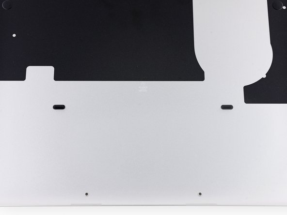
    • The lower case is connected to the upper case with two plastic clips near its center.

    • During reassembly, gently push down the center of the lower case to reattach the two plastic clips.

  4. Этот шаг не переведен. Помогите перевести

    : шаг 4, изображение 1 из 1
    • If necessary, remove the plastic cover adhered to the battery contact board.

  5. Этот шаг не переведен. Помогите перевести

    : шаг 5, изображение 1 из 2 : шаг 5, изображение 2 из 2
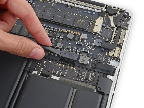
    • Use the flat end of a spudger to lift the battery connector straight up out of its socket on the logic board.

    • Be sure you lift up only on the connector itself, not the socket, or you risk permanent damage to the logic board.

  6. Этот шаг не переведен. Помогите перевести

    : шаг 6, изображение 1 из 1
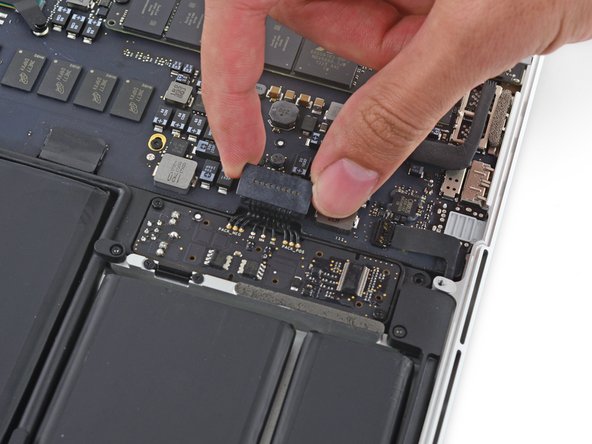
    • Bend the battery connector up out of the way to prevent accidental contact with its socket during your repair.

  7. Этот шаг не переведен. Помогите перевести

    : шаг 7, изображение 1 из 2 : шаг 7, изображение 2 из 2
    • Insert the tip of a spudger under the left speaker cable near the connector and lift it up out of its socket on the logic board.

  8. Этот шаг не переведен. Помогите перевести

    : шаг 8, изображение 1 из 1
    • Remove the following screws securing the left speaker to the upper case:

    • One 5.7 mm T5 Torx screw

    • One 6.5 mm T5 Torx screw

    • One 3.8 mm T5 Torx screw

  9. Этот шаг не переведен. Помогите перевести

    : шаг 9, изображение 1 из 3 : шаг 9, изображение 2 из 3 : шаг 9, изображение 3 из 3
    • Lift the corner of the left speaker up and slide it out around the battery to remove it from the upper case.

    • Be careful not to snag the speaker cable on the screw hole post in the side of the case.

Финишная черта

83 участников успешно повторили данное руководство.

Sam Goldheart

Участник с: 10/18/12

465 762 Репутация

Автор 538 руководств

Команда

iFixit Участник iFixit

Staff

135 членов

Автор 16 817 руководств

16 Комментариев

A very straightforward repair. Thanks for the excellent instructions!

Andrew - Ответить

is the same process for the right speaker? thank you very much Sam Lionheart!

Tonino - Ответить

Pretty much, there's another cable to disconnect, but we have a whole guide for the right speaker, too! Best of luck!

Sam Goldheart -

Hi! Are the L/R speakers compatible with the 13" Early 2015 models?

fylungster - Ответить

Great guide. I was able to dismantle the speaker and fixed the blown left speaker. Fit it back and it worked. Now, i’ll do that for the right speaker.

iamleongch - Ответить

Добавить комментарий

Просмотр статистики:

За последние 24часов: 14

За последние 7 дней: 101

За последние 30 дней: 360

За всё время: 75,755