Эта версия возможно содержит некорректные исправления. Переключить на последнюю проверенную версию.
Выберете то, что вам нужно
-
Этот шаг не переведен. Помогите перевести
-
Use a T3 Torx driver to remove the two 1.9 mm screws from the keyboard connector bracket.
-
-
Этот шаг не переведен. Помогите перевести
-
Use a spudger to disconnect the keyboard connector by prying it straight up from the logic board.
-
-
Этот шаг не переведен. Помогите перевести
-
Remove the two 2.9 mm T3 Torx screws securing the aluminum cover on top of the main display cable.
-
Remove the cover.
-
-
Этот шаг не переведен. Помогите перевести
-
Remove the two 1.7 mm T3 Torx screws securing the aluminum cover on top of the display cable flex connector.
-
Remove the cover.
-
-
Этот шаг не переведен. Помогите перевести
-
Pry the display board flex cable straight up from its socket to disconnect it from the display board.
-
-
Этот шаг не переведен. Помогите перевести
-
Using a T3 Torx driver:
-
Remove two 1.4 mm screws from the Thunderbolt port connector bracket on the left.
-
Remove two more 1.4 mm screws from the Thunderbolt port connector bracket on the right.
If you are trying to replace the Thunderbolt port boards, you have to finish removing the entire logic board in order to get to the 2 screws holding each board in place. You can leave the battery and track pad in place though.
Apple used poor quality boards for the thunderbolt boards so they will definitely wear out over time. Make sure you replace them with metal boards and your USB C cable will click in nice and tight for a really long time.
-
-
Этот шаг не переведен. Помогите перевести
-
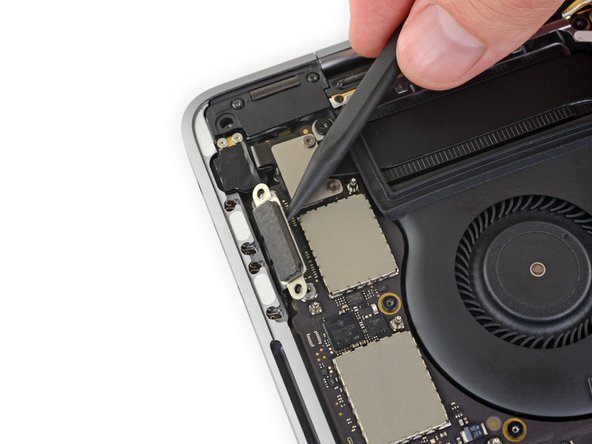
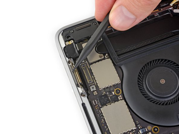
Use a spudger to disconnect the left-side Thunderbolt port connector by prying it straight up from the logic board.
-
Gently push the connector aside so it won't interfere with logic board removal.
-
-
Этот шаг не переведен. Помогите перевести
-
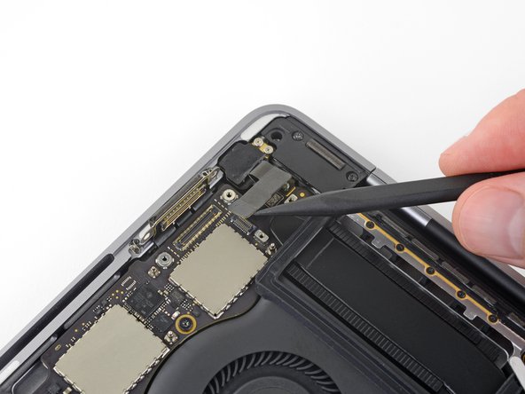
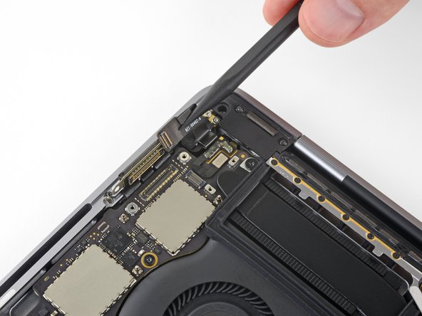
Repeat for the right-side Thunderbolt port connector, prying it up from the inside edge and pushing it carefully aside.
-
-
Этот шаг не переведен. Помогите перевести
-
Use a T3 Torx driver to remove the two 1.9 mm screws from the cover bracket securing the Touch ID and 3.5 mm audio jack connectors.
-
-
Этот шаг не переведен. Помогите перевести
-
Use a spudger to disconnect the 3.5 mm audio jack flex cable by prying it straight up from the logic board.
-
Gently push the flex cable aside.
-
-
Этот шаг не переведен. Помогите перевести
-
Disconnect the Touch ID and power button flex cable by prying it straight up from the logic board.
-
-
Этот шаг не переведен. Помогите перевести
-
Apply mild heat using an iOpener, heat gun, or hair dryer to soften the adhesive under the power button/Touch ID flex cable.
-
-
Этот шаг не переведен. Помогите перевести
-
Carefully slide an opening pick under the flex cable to separate it from the logic board, and push it carefully aside.
-
If you have trouble, don't force it—apply a little more heat and try again.
First let me thank you for this AMAZING guide which helped me a lot to achieve an almost successful battery replacement… I’m saying “almost” because, as you write in red letters, I wasn’t careful enough and my Touch ID cable got damaged.
Do you have any idea on how much should such a repair cost?
I know that only apple stores or authorized service providers can perform such a repair…
Thanks again!
Boy that’s a tough one :( It’s among the most problematic of all components to replace, because the fingerprint sensor is cryptographically paired to the logic board. The best option might be to get in touch with a skilled microsolderer and ask if they can take a look at the cable and try to repair the traces. Apart from that, the only options I’m aware of would be to pay Apple whatever they demand for a repair (no idea, but most likely a lot), or replace both the sensor and the entire logic board with another set that is already paired and undamaged. Wish I could be more help. Good luck!
Difficult though it may be, as a retired fixer, and amazed at the new tiny tiny parts, I am even more amazed at this new cooperative culture of fixers. The depth of helpful detail is amazing. The new environment of cheap special tools, and amazingly detailed hires pics is a powerful new repair meme. I used i-fixit for my first MBAir, but haven’t the skills for this, my current mac. But this addition, the carefully inserted comments of users, and the skills and cooperative attitude of you all, is quite amazing. And I watch and admire. Well done, you.
This cable has a metal plate that is PART OF THE CABLE. It is initially invisible, and can easily be mistaken for part of the logic board upon which it is adhered. As you begin to try to peel it up, make certain that your tool is also making its way beneath that integral thin metal plate. There are chip components that will delaminate from the cable if you attempt to lift it, or if your prying tool happens to not make it under the plate.
-
-
-
Этот шаг не переведен. Помогите перевести
-
Use a T3 Torx driver to remove the 1.9 mm screw from the Touch Bar digitizer connector bracket.
-
-
Этот шаг не переведен. Помогите перевести
-
Use a spudger to disconnect the Touch Bar digitizer by prying its connector straight up from the logic board.
-
-
Этот шаг не переведен. Помогите перевести
-
Use a T3 Torx driver to remove two 1.9 mm screws from the Touch Bar display connector bracket.
-
-
Этот шаг не переведен. Помогите перевести
-
Use a spudger to disconnect the Touch Bar display connector by prying it straight up from the logic board.
-
-
Этот шаг не переведен. Помогите перевести
-
Peel back any tape covering the microphone connector socket.
-
-
Этот шаг не переведен. Помогите перевести
-
Open the locking flap on the microphone cable's ZIF connector by prying it straight up from the logic board.
-
-
Этот шаг не переведен. Помогите перевести
-
Disconnect the microphone cable by pulling it back—away from the fan—until it slides out of its socket.
-
If possible, pull on the attached tape, rather than on the cable itself.
-
-
Этот шаг не переведен. Помогите перевести
-
Peel back any tape covering the connector for the left-side tweeter.
-
-
Этот шаг не переведен. Помогите перевести
-
Flip open the locking flap for the left-side tweeter ZIF connector by prying it straight up from the logic board.
-
-
Этот шаг не переведен. Помогите перевести
-
Disconnect the cable by pulling it towards the tweeter until it slides out of its socket.
-
If possible, pull on the attached tape rather than the cable itself.
-
-
Этот шаг не переведен. Помогите перевести
-
Peel back any tape covering the socket for the left main speaker.
For me, the main speaker tape on both sides tore loose, which is a real shame, because those are the two hardest to get back in - they're very short and stiff.
Important safety tip: On my laptop, the cables have two semicircular notches near the end. You can tell when they're fully-inserted when the notches are inside the connector.
-
-
Этот шаг не переведен. Помогите перевести
-
Flip open the locking flap for the left main speaker ZIF connector by prying it straight up from the logic board.
-
-
Этот шаг не переведен. Помогите перевести
-
Disconnect the left main speaker cable by pulling it toward the tweeter until it slides free from its socket.
-
Remember to pull on the attached tape, not the cable.
-
-
Этот шаг не переведен. Помогите перевести
-
Repeat the previous six steps to disconnect the opposite tweeter and main speaker, on the right.
-
Begin by peeling back any tape covering the tweeter connector.
This step seems redundant as those six steps get repeated in detail anyway after this step.
-
-
Этот шаг не переведен. Помогите перевести
-
Flip open the locking flap for the right-side tweeter ZIF connector by prying it straight up from the logic board.
-
-
Этот шаг не переведен. Помогите перевести
-
Disconnect the cable by pulling it towards the tweeter until it slides out of its socket.
-
Remember to pull on the tape if possible—not the actual cable.
-
-
Этот шаг не переведен. Помогите перевести
-
Peel back any tape covering the connector for the right-side main speaker.
-
-
Этот шаг не переведен. Помогите перевести
-
Flip open the locking flap for the right-side main speaker ZIF connector by prying it straight up from the logic board.
-
-
Этот шаг не переведен. Помогите перевести
-
Pull the right-side main speaker cable toward the tweeter until it slides free from its socket.
-
-
Этот шаг не переведен. Помогите перевести
-
Disconnect the first antenna cable by prying it straight up from its socket.
-
Carefully slide your tweezers or the flat end of your spudger underneath the cable until it's near the socket, and then gently twist or pry up to disconnect it.
-
-
Этот шаг не переведен. Помогите перевести
-
Repeat the previous step to disconnect the two remaining antenna cables.
Reconnecting is very tricky. It doesn't take much force to push down, but the connectors have to be perfectly aligned. You won't really feel it snap into place, but it will stay put and resist wiggling.
Agreed, very tricky step. I found the two slightly longer leads easier to reattach. Then I used them as a visual guide to attach the small lead. It helped to slightly bend the lead. Glenn is correct, it doesn’t take much pressure to attach but the leads have to be perfectly aligned. Be careful if you test the fit, very easy to pry back off.
-
-
Этот шаг не переведен. Помогите перевести
-
Use a T5 Torx driver to remove the 2.9 mm screw securing the antenna cable bundle.
-
-
Этот шаг не переведен. Помогите перевести
-
Remove all ten screws securing the logic board assembly:
-
Three 2.5 mm Torx T3 screws
-
Five 2.9 mm Torx T5 screws
-
Two 3.0 mm Torx T5 screws
-
-
Этот шаг не переведен. Помогите перевести
-
Peel up (but don't remove) the two rubber vibration damping strips from the adhesive holding them to the fans.
-
If needed, apply mild heat with an iOpener, hair dryer, or heat gun to soften the adhesive and make the dampers easier to separate.
Mine had no adhesive on them at all. You only need to make sure they are loosened from the fan shroud. They come out with the logic board assembly.
-
-
Этот шаг не переведен. Помогите перевести
-
Lift from the left side to remove the logic board assembly.
Wichtig !!
Vorher den Display Anschluß (hinten mitte) Abschrauben und lösen.
2x bleche mit jeweils 2 Scxhrauben
Ist nachgetragen. Danke!
What just happened… While I was removing the logic board one of the small black boxes from the bottom right just fell off. I am not sure but I think it is a capacitor - it says KO 336 16K 723. It just fell, I did not even touch this part… Maybe it was broken when I opened up the case in the beginning, but I did not notice it then.
Did I just break my laptop?
Translation
Important !!
First unscrew and loosen the display connection (rear center).
2x plates with 2 screws each
@Glendstone You are absolutely right. This is a key feature they forgot to explain.
The feedbacis has possibly already been addressed in step 27 as it was already fully disconnected when I got to this step.
-
-
Этот шаг не переведен. Помогите перевести
-
Check the alignment of the rubber vibration dampers, and adjust them as needed.
-
Feed the antenna cable bundle through the gap between the logic board and heat sink, and make sure it lines up correctly as you lower the board into place.
-
Verify that no cables get trapped under the board as you install it. Check each marked location carefully.
-


T4 worked best here for me.
Benjamin Bradshaw - Ответить