Эта версия возможно содержит некорректные исправления. Переключить на последнюю проверенную версию.
Выберете то, что вам нужно
-
Этот шаг не переведен. Помогите перевести
-
If your MacBook is running Big Sur v11.1 or later, disabling Auto Boot may not work. You can proceed normally, but make sure to disconnect the battery as soon as you're inside.
-
Use a P5 Pentalobe driver to remove the six screws securing the lower case:
-
Two 6.8 mm screws
-
Two 5.3 mm screws
-
Two 3.4 mm screws
-
-
Этот шаг не переведен. Помогите перевести
-
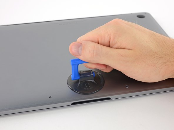
Apply a suction handle to the lower case near the front-center area of the MacBook Pro.
-
Lift the suction handle to create a slight separation between the lower case and the chassis.
-
-
Этот шаг не переведен. Помогите перевести
-
Insert one corner of an opening pick into the space between the lower case and the chassis.
-
Slide the opening pick around the nearest corner and halfway up the side of the case.
-
-
Этот шаг не переведен. Помогите перевести
-
Repeat the previous step on the opposite side, sliding your opening pick under the lower case and up the side to pop the second clip free.
-
-
Этот шаг не переведен. Помогите перевести
-
Insert your opening pick once again under the front edge of the lower case, near one of the two centermost screw holes.
-
Give the pick a firm twist to pop free the third clip securing the lower case to the chassis.
-
Repeat this procedure near the other of the two centermost screw holes, popping the fourth clip free.
-
-
Этот шаг не переведен. Помогите перевести
-
Pull the lower case firmly towards the front of the MacBook (away from the hinge area) to separate the last of the clips securing the lower case.
-
-
Этот шаг не переведен. Помогите перевести
-
Remove the lower case.
-
Set it in place and align the sliding clips near the display hinge. Press down and slide the cover toward the hinge. It should stop sliding as the clips engage.
-
When the sliding clips are fully engaged and the lower case looks correctly aligned, press down firmly on the lower case to engage the four hidden clips underneath. You should feel and hear them snap into place.
-
-
Этот шаг не переведен. Помогите перевести
-
Carefully peel up the large piece of tape covering the battery connector, on the edge of the logic board nearest the battery.
-
Remove the tape.
-
-
Этот шаг не переведен. Помогите перевести
-
Gently peel back the small piece of tape covering the battery board data cable connector.
-
-
-
Этот шаг не переведен. Помогите перевести
-
Use the tip of a spudger to flip up the small black locking tab securing the cable in its connector.
-
-
Этот шаг не переведен. Помогите перевести
-
Disconnect the battery board data cable by sliding it out from its socket.
-
Slide parallel to the logic board, in the direction of the cable.
-
-
Этот шаг не переведен. Помогите перевести
-
Fold the battery board data cable back and out of the way.
-
-
Этот шаг не переведен. Помогите перевести
-
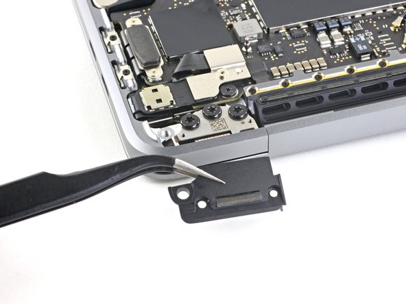
Use a T5 Torx driver to remove the 3.7 mm pancake screw securing the battery power connector.
-
-
Этот шаг не переведен. Помогите перевести
-
Use a spudger to gently lift the battery power connector, disconnecting the battery.
-
Lift the connector high enough so that it stays separated from its socket.
-
-
Этот шаг не переведен. Помогите перевести
-
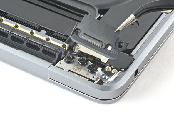
Remove the four 3.3 mm T3 Torx screws securing the plastic covers on top of the display hinges.
-
-
Этот шаг не переведен. Помогите перевести
-
Remove the two 3.1 mm T3 Torx screws securing the aluminum cover on top of the main display cable.
-
Remove the cover.
-
-
Этот шаг не переведен. Помогите перевести
-
Remove the two 1.7 mm T3 Torx screws securing the aluminum cover on top of the display cable flex connector.
-
Remove the cover.
-
-
Этот шаг не переведен. Помогите перевести
-
Pry the display board flex cable straight up from its socket to disconnect it from the display board.
-
-
Этот шаг не переведен. Помогите перевести
-
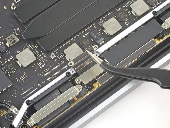
Remove the four 1.5 mm T3 Torx screws securing the two aluminum covers on top of the two display cable connectors.
-
Use a pair of tweezers to remove the two aluminum covers.
-
-
Этот шаг не переведен. Помогите перевести
-
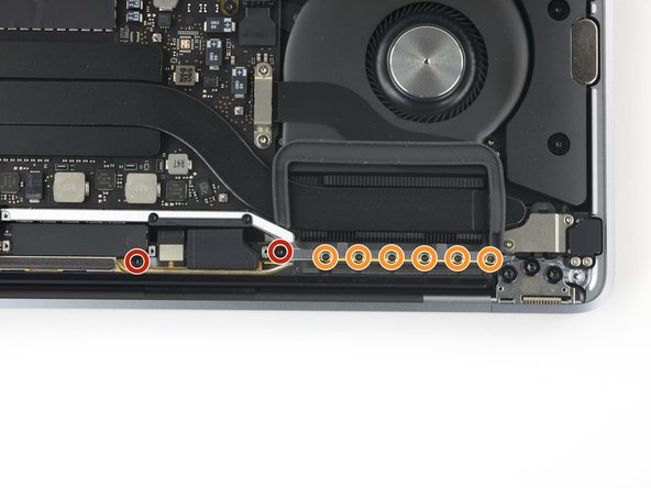
Remove the four 3.3 mm T5 Torx screws (two on each side) which secure the antenna cable assembly.
-
Also remove the twelve 1.1 mm P2 pentalobe screws (six on each side).
-
-
Этот шаг не переведен. Помогите перевести
-
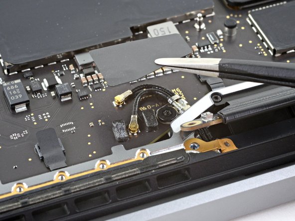
Use a pair of tweezers to remove the plastic antenna cable cover.
-
-
Этот шаг не переведен. Помогите перевести
-
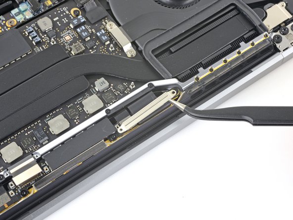
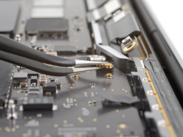
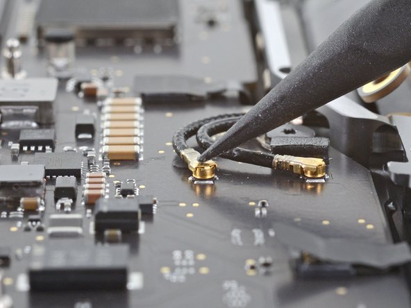
Carefully disconnect the two antenna coax cables by prying them straight up from the logic board.
-
Slide your tweezers or the flat end of your spudger underneath each cable until it's near the socket, and then gently twist or pry up to disconnect it.
-
-
Этот шаг не переведен. Помогите перевести
-
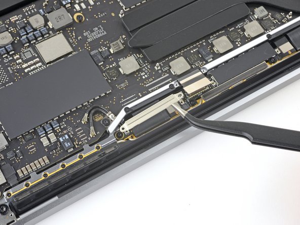
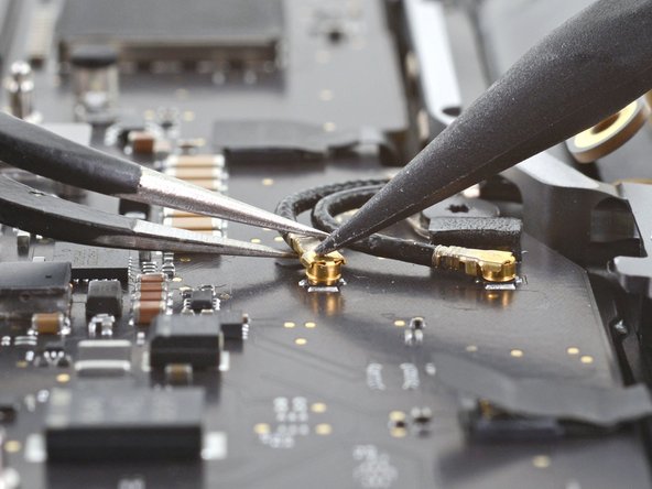
Remove the 3.7 mm T5 Torx screw securing the two antenna coax cables to the main board.
-
-
Этот шаг не переведен. Помогите перевести
-
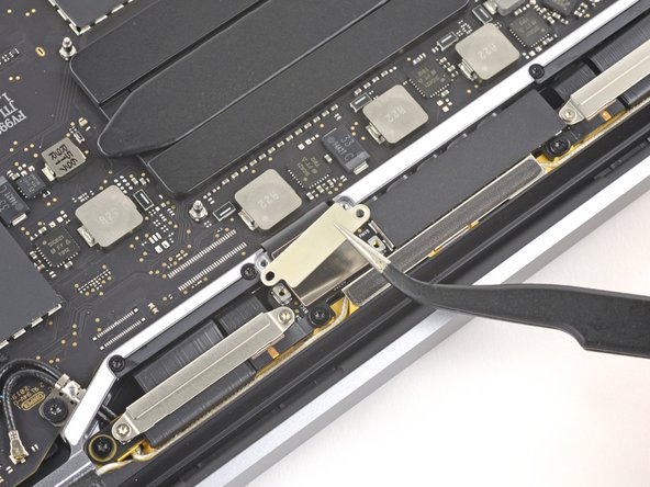
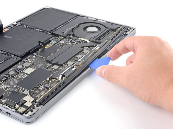
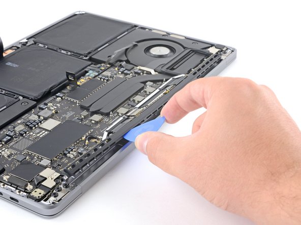
Use an opening pick to lever out the antenna cable assembly in the areas shown.
-
-
Этот шаг не переведен. Помогите перевести
-
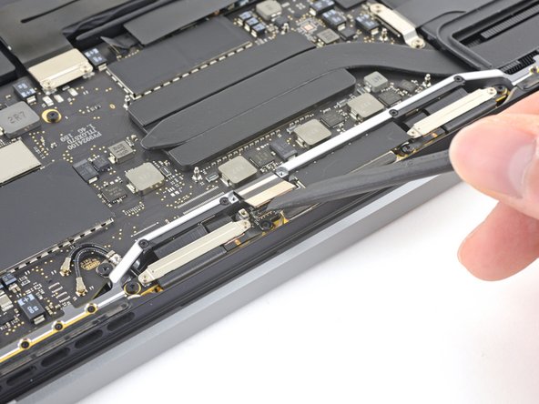
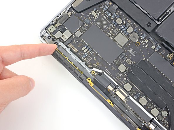
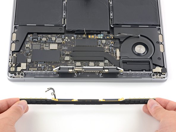
Carefully remove the antenna assembly while simultaneously feeding the antenna cable bundle out from underneath the heat pipe.
-
Remove the antenna cable assembly.
-