Эта версия возможно содержит некорректные исправления. Переключить на последнюю проверенную версию.
Выберете то, что вам нужно
-
Этот шаг не переведен. Помогите перевести
-
Remove the following 10 screws securing the lower case to the MacBook Pro 13" Unibody:
-
Seven 3 mm Phillips screws.
-
Three 13.5 mm Phillips screws.
-
-
Этот шаг не переведен. Помогите перевести
-
Slightly lift the lower case and push it toward the rear of the computer to free the mounting tabs.
-
-
Этот шаг не переведен. Помогите перевести
-
Use the flat end of a spudger to lift the battery connector up out of its socket on the logic board.
-
-
Этот шаг не переведен. Помогите перевести
-
Use a spudger to pry up the fan connector out of its socket on the logic board.
-
-
Этот шаг не переведен. Помогите перевести
-
Remove the following three screws:
-
One 7 mm T6 Torx screw
-
Two 5.4 mm T6 Torx screws
-
-
Этот шаг не переведен. Помогите перевести
-
Grab the plastic pull tab secured to the display data cable lock and rotate it toward the DC-In side of the computer.
-
Gently pull the display data cable connector away parallel to the board.
-
-
Этот шаг не переведен. Помогите перевести
-
Remove the following two screws securing the display data cable bracket to the upper case:
-
One 8.6 mm Phillips
-
One 5.6 mm Phillips
-
Lift the display data cable bracket out of the upper case.
-
-
-
Этот шаг не переведен. Помогите перевести
-
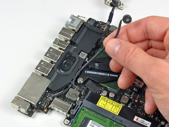
Use the flat end of a spudger to pry the subwoofer and right speaker connector up off the logic board.
-
-
Этот шаг не переведен. Помогите перевести
-
Pull the camera cable connector toward the optical drive to disconnect it from the logic board.
-
-
Этот шаг не переведен. Помогите перевести
-
Use the flat end of a spudger to pry the optical drive, hard drive, and trackpad cable connectors up off the logic board.
-
-
Этот шаг не переведен. Помогите перевести
-
Use your fingernail or the tip of a spudger to flip up the cable retaining flap on the ZIF socket for the keyboard ribbon cable.
-
Use your spudger to slide the keyboard ribbon cable out of its socket.
-
-
Этот шаг не переведен. Помогите перевести
-
Peel the small strip of black tape off the keyboard backlight ribbon cable socket.
-
-
Этот шаг не переведен. Помогите перевести
-
Use the tip of a spudger to flip up the cable retaining flap on the ZIF socket for the keyboard backlight ribbon cable.
-
Use your spudger to slide the keyboard backlight ribbon cable out of its socket.
-
-
Этот шаг не переведен. Помогите перевести
-
Use the flat end of a spudger to pry the battery indicator cable connector up off the logic board.
-
-
Этот шаг не переведен. Помогите перевести
-
Use the tip of a spudger to pry the microphone off the adhesive attaching it to the upper case.
-
-
Этот шаг не переведен. Помогите перевести
-
Remove the following screws:
-
Two 7 mm T6 Torx screws from the DC-In board
-
Five 3.3 mm T6 Torx screws
-
Two 4 mm T6 Torx screws
-
-
Этот шаг не переведен. Помогите перевести
-
Remove the following Tri-point screws securing the battery to the upper case:
-
One 5.5 mm Tri-point screw
-
One 13.5 mm Tri-point screw
-
Lift the battery out of the upper case.
-
-
Этот шаг не переведен. Помогите перевести
-
Lift the logic board from its left edge and raise it until the ports clear the side of the upper case.
-
Pull the logic board away from the side of the upper case and remove it, minding the DC-In board that may get caught.
-
-
Этот шаг не переведен. Помогите перевести
-
Peel the tape off covering the microphone cable connector.
-
-
Этот шаг не переведен. Помогите перевести
-
Use the flat end of a spudger to pry the microphone cable connector up off the logic board.
-
Deroute the microphone cable from the channel in the left speaker.
-
-
Этот шаг не переведен. Помогите перевести
-
Remove the strip of tape covering the left speaker cable connector.
-
-
Этот шаг не переведен. Помогите перевести
-
Use the flat end of a spudger to pry the left speaker connector up off the logic board.
-
-
Этот шаг не переведен. Помогите перевести
-
Carefully peel the left speaker assembly off the adhesive securing it to the logic board.
-


Отменить: Я не выполнил это руководство.
14 участников успешно повторили данное руководство.
