Этот документ имеет более свежие изменения. Перейти к последней непроверенной версии.
Введение
Use this guide to completely replace your upper case.
Выберете то, что вам нужно
-
-
Remove the following 10 screws securing the lower case to the MacBook Pro 13" Unibody:
-
Seven 3 mm Phillips screws.
-
Three 13.5 mm Phillips screws.
-
-
-
Slightly lift the lower case and push it toward the rear of the computer to free the mounting tabs.
-
-
-
Use the flat end of a spudger to lift the battery connector up out of its socket on the logic board.
-
-
-
Use a spudger to pry up the fan connector out of its socket on the logic board.
-
-
-
Remove the following three screws:
-
One 7 mm T6 Torx screw
-
Two 5.4 mm T6 Torx screws
-
-
-
Grab the plastic pull tab secured to the display data cable lock and rotate it toward the DC-In side of the computer.
-
Gently pull the display data cable connector away parallel to the board.
-
-
-
Remove the following two screws securing the display data cable bracket to the upper case:
-
One 8.6 mm Phillips
-
One 5.6 mm Phillips
-
Lift the display data cable bracket out of the upper case.
-
-
-
Use the flat end of a spudger to pry the subwoofer and right speaker connector up off the logic board.
-
-
-
Pull the camera cable connector toward the optical drive to disconnect it from the logic board.
-
-
-
Use the flat end of a spudger to pry the optical drive, hard drive, and trackpad cable connectors up off the logic board.
-
-
-
-
Use your fingernail or the tip of a spudger to flip up the cable retaining flap on the ZIF socket for the keyboard ribbon cable.
-
Use your spudger to slide the keyboard ribbon cable out of its socket.
-
-
-
Peel the small strip of black tape off the keyboard backlight ribbon cable socket.
-
-
-
Use the tip of a spudger to flip up the cable retaining flap on the ZIF socket for the keyboard backlight ribbon cable.
-
Use your spudger to slide the keyboard backlight ribbon cable out of its socket.
-
-
-
Use the flat end of a spudger to pry the battery indicator cable connector up off the logic board.
-
-
-
Use the tip of a spudger to pry the microphone off the adhesive attaching it to the upper case.
-
-
-
Remove the following screws:
-
Two 7 mm T6 Torx screws from the DC-In board
-
Five 3.3 mm T6 Torx screws
-
Two 4 mm T6 Torx screws
-
-
-
Remove the following Tri-point screws securing the battery to the upper case:
-
One 5.5 mm Tri-point screw
-
One 13.5 mm Tri-point screw
-
Lift the battery out of the upper case.
-
-
-
Lift the logic board from its left edge and raise it until the ports clear the side of the upper case.
-
Pull the logic board away from the side of the upper case and remove it, minding the DC-In board that may get caught.
-
-
-
Remove two Phillips screws securing the hard drive bracket to the upper case.
-
Lift the the retaining bracket out from the upper case.
-
-
-
Lift the hard drive from its free edge and pull it out of the chassis, minding the cable attaching it to the computer.
-
-
-
Disconnect the hard drive by pulling the hard drive cable connector away from the drive.
-
-
-
Remove the following four screws securing the hard drive and IR sensor cable to the upper case:
-
Two 1.5 mm Phillips screws.
-
Two 4 mm Phillips screws.
-
Slide the hard drive and IR sensor bracket away from the edge of the upper case.
-
Carefully peel the hard drive and IR sensor cable from the upper case.
-
-
-
Remove the following screws securing the subwoofer to the upper case:
-
One 3.8 mm Phillips screw.
-
One 5 mm Phillips screw
-
Lift the subwoofer off the optical drive, and set it above the computer.
-
-
-
Remove the two 10 mm Phillips screws securing the camera cable bracket to the upper case.
-
Lift the camera cable bracket out of the upper case.
-
-
-
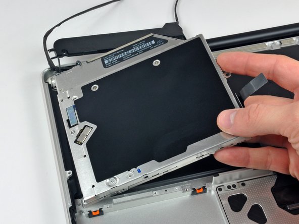
Remove the three 2.5 mm Phillips screws securing the optical drive to the upper case.
-
Lift the optical drive from its right edge and pull it out of the computer.
-
-
-
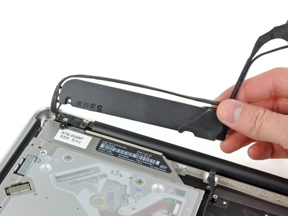
Peel back the small piece of black tape covering the right speaker cable.
-
Be careful, as the power button ribbon cable is directly under this piece of tape.
-
-
-
Use the tip of a spudger to pry the right speaker up off the adhesive securing it to the upper case.
-
-
-
Remove the two outer T8 Torx screws securing each side of the display bracket to the upper case (4 screws total).
-
-
-
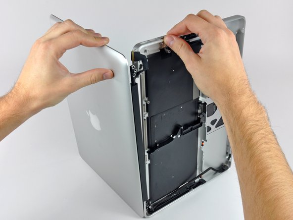
Open your MacBook so the display is perpendicular to the upper case.
-
Place your opened MacBook on a table as pictured.
-
While holding the display and upper case together with your left hand, remove the T8 Torx screw from the lower display bracket.
-
-
-
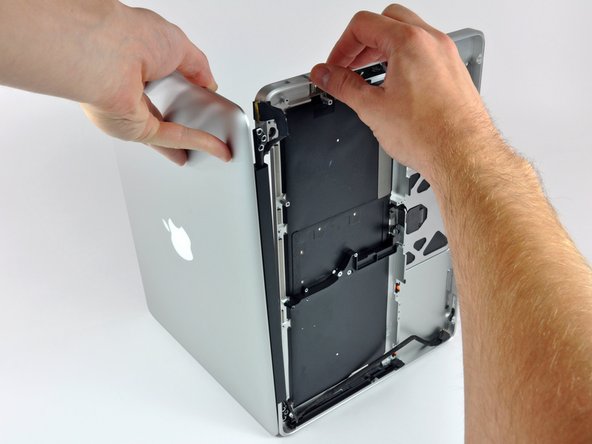
Be sure to hold the display and upper case together with your left hand. Failure to do so may cause the freed display/upper case to fall, potentially damaging each component.
-
Remove the last remaining T8 Torx screw securing the display to the upper case.
-
-
-
Grab the upper case with your right hand and rotate it slightly toward the top of the display so the upper display bracket clears the edge of the upper case.
-
Rotate the display slightly away from the upper case.
-
Lift the display up and away from the upper case, minding any brackets or cables that may get caught.
-


To reassemble your device, follow these instructions in reverse order.
To reassemble your device, follow these instructions in reverse order.
Отменить: Я не выполнил это руководство.
9 участников успешно повторили данное руководство.
