Эта версия возможно содержит некорректные исправления. Переключить на последнюю проверенную версию.
Выберете то, что вам нужно
-
-
Выкрутите 10 выделенных шурупов:
-
Три 14.4 mm Phillips #00 шурупа
-
Три 3.5 mm Phillips #00 шурупа
-
Четыре 3.5 mm Phillips #00 шурупа с бортиками
-
-
Этот шаг не переведен. Помогите перевести
-
Use your fingers to pry the lower case away from the body of the MacBook near the vent.
-
Remove the lower case.
-
-
Этот шаг не переведен. Помогите перевести
-
Use the edge of a spudger to pry the battery connector upwards from its socket on the logic board.
-
-
Этот шаг не переведен. Помогите перевести
-
Bend the battery cable slightly away from its socket on the logic board so it does not accidentally connect itself while you work.
-
-
Этот шаг не переведен. Помогите перевести
-
Use the edge of a spudger to gently pry the fan connector up and out of its socket on the logic board.
-
-
Этот шаг не переведен. Помогите перевести
-
Remove the following three screws securing the fan to the logic board:
-
One 7.2 mm T6 Torx screw
-
Two 5.3 mm T6 Torx screws
-
-
Этот шаг не переведен. Помогите перевести
-
Lift the fan out of its recess in the logic board, minding its cable that may get caught.
-
-
Этот шаг не переведен. Помогите перевести
-
Use the tip of a spudger to pull the right speaker/subwoofer cable out from under the retaining finger molded into the upper case.
-
Pull the right speaker/subwoofer cable upward to lift the connector out of its socket on the logic board.
-
-
Этот шаг не переведен. Помогите перевести
-
Disconnect the following four cables:
-
AirPort/Bluetooth cable
-
Optical drive cable
-
Hard drive cable
-
Trackpad cable
-
-
Этот шаг не переведен. Помогите перевести
-
Use your fingernail to flip up the retaining flap on the keyboard ribbon cable ZIF socket.
-
Use the tip of a spudger to pull the keyboard ribbon cable out of its socket.
-
-
Этот шаг не переведен. Помогите перевести
-
If present, remove the small strip of black tape covering the keyboard backlight cable socket.
-
-
Этот шаг не переведен. Помогите перевести
-
Use the tip of a spudger or your fingernail to flip up the retaining flap on the keyboard backlight ribbon cable ZIF socket.
-
Pull the keyboard backlight ribbon cable out of its socket.
-
-
Этот шаг не переведен. Помогите перевести
-
Use the flat end of a spudger to pry the sleep sensor/battery indicator connector up from its socket on the logic board.
-
-
Этот шаг не переведен. Помогите перевести
-
Grab the plastic pull tab secured to the display data cable lock and rotate it toward the DC-In side of the computer.
-
Pull the display data cable straight out of its socket on the logic board.
-
-
Этот шаг не переведен. Помогите перевести
-
Remove the following nine screws:
-
Five 3.6 mm T6 Torx screws
-
Two 4.3 mm T6 Torx screws
-
Two 7.2 mm T6 Torx screws
-
Five 3.0 mm T6 screws
-
Two 3.6 mm T6 screws
-
Two 6.7 mm T6 screws
-
-
Этот шаг не переведен. Помогите перевести
-
Remove the following two screws:
-
One 8.6 mm Phillips screw
-
One 5.5 mm Phillips screw
-
Remove the display data cable retainer from the upper case.
-
-
-
Этот шаг не переведен. Помогите перевести
-
Use the tip of a spudger to gently peel the microphone off the adhesive securing it to the upper case.
-
-
Этот шаг не переведен. Помогите перевести
-
Minding the many connectors near its edges, lift the logic board from the end nearest the optical drive.
-
Without flexing the board, maneuver it out of the upper case, minding the flexible connection to the DC-In board that may get caught in the upper case.
-
Remove the logic board.
-
-
Этот шаг не переведен. Помогите перевести
-
Remove the following two screws:
-
One 5.6 mm Tri-point screw
-
One 13 mm Tri-point screw
-
-
Этот шаг не переведен. Помогите перевести
-
Carefully peel the battery warning label off the upper case between the battery and the optical drive.
-
-
Этот шаг не переведен. Помогите перевести
-
Use the attached plastic pull tab to help remove the battery from the upper case.
-
-
Этот шаг не переведен. Помогите перевести
-
Remove the two Phillips screws securing the hard drive bracket to the upper case.
-
Remove the hard drive bracket.
-
-
Этот шаг не переведен. Помогите перевести
-
Use the attached pull tab to lift the hard drive out of the upper case.
-
Pull the hard drive cable away from the body of the hard drive.
-
Remove the hard drive.
-
-
Этот шаг не переведен. Помогите перевести
-
Remove the following four screws:
-
Two 3 mm Phillips screws
-
Two 9.7 mm Phillips screws
-
-
Этот шаг не переведен. Помогите перевести
-
Carefully peel up the thin IR sensor/sleep LED ribbon cable from the adhesive securing it to the upper case.
-
-
Этот шаг не переведен. Помогите перевести
-
Pull the front hard drive bracket containing the IR sensor/sleep LED away from the front edge of the upper case.
-
Remove the hard drive cable.
-
-
Этот шаг не переведен. Помогите перевести
-
Carefully move the AirPort/Bluetooth ribbon cable out of the way as you peel the camera cable off the adhesive securing it to the subwoofer and the AirPort/Bluetooth bracket.
-
De-route the camera cable out from under the retaining finger molded into the AirPort/Bluetooth bracket.
-
-
Этот шаг не переведен. Помогите перевести
-
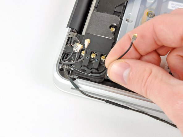
Disconnect the four antenna connectors boxed in red in the first picture.
-
To do so, use the tip of a spudger to pry their connectors up from the sockets on the AirPort/Bluetooth board.
-
De-route each of the cables from their channels in the AirPort/Bluetooth bracket.
-
-
Этот шаг не переведен. Помогите перевести
-
Remove the following five screws:
-
Two 10.3 mm Phillips screws
-
Two 3.1 mm Phillips screws
-
One 5 mm Phillips screw
-
-
Этот шаг не переведен. Помогите перевести
-
Pull the AirPort/Bluetooth assembly and the Subwoofer upward near the center of the side of the optical drive until they clear each other.
-
Remove the AirPort/Bluetooth board assembly.
-
-
Этот шаг не переведен. Помогите перевести
-
Remove the three 2.7 mm Phillips screws securing the optical drive to the upper case.
-
-
Этот шаг не переведен. Помогите перевести
-
Lift the optical drive from the edge nearest the display and remove it from the upper case.
-
-
Этот шаг не переведен. Помогите перевести
-
Use a plastic opening tool or another thin prying object to carefully pry the right speaker up from the adhesive securing it to the upper case.
-
Pry up along the edge of the right speaker until it is separated from the upper case.
-
-
Этот шаг не переведен. Помогите перевести
-
Pull the right speaker out from under the optical drive opening.
-
-
Этот шаг не переведен. Помогите перевести
-
Remove two of the three 6 mm T8 Torx screws securing the right side of the display to the upper case.
-
-
Этот шаг не переведен. Помогите перевести
-
Remove the small piece of foam tape covering the left display hinge screws.
-
-
Этот шаг не переведен. Помогите перевести
-
Remove two of the three 6 mm T8 Torx screws securing the left side of the display to the upper case.
-
-
Этот шаг не переведен. Помогите перевести
-
Open your MacBook Pro so the display is perpendicular to the upper case.
-
Place your opened MacBook Pro on a table as pictured.
-
While holding the display and upper case together with your left hand, remove the remaining T8 Torx screw from the lower display bracket.
-
-
Этот шаг не переведен. Помогите перевести
-
Remove the last remaining T8 Torx screw securing the display to the upper case.
-
-
Этот шаг не переведен. Помогите перевести
-
Grab the upper case with your right hand and rotate it slightly toward the top of the display so the upper display bracket clears the edge of the upper case.
-
Rotate the display slightly away from the upper case.
-
Lift the display up and away from the upper case, minding any brackets or cables that may get caught.
-
Upper case remains.
-
-
Этот шаг не переведен. Помогите перевести
-
Remove the four 1.2 mm Phillips screws highlighted in red.
-
-
Этот шаг не переведен. Помогите перевести
-
Carefully dislodge the edge of the trackpad closest to the keyboard from its recess in the upper case by pushing it away from the brackets attached to the upper case.
-
De-route the trackpad cable through its slot cut into the upper case.
-
-
Этот шаг не переведен. Помогите перевести
-
Pull the trackpad away from the outer edge of the upper case.
-
Remove the trackpad and set it aside.
-
-
Этот шаг не переведен. Помогите перевести
-
Use a T6 Torx screwdriver to loosely install the 1.1 mm set screw included with your new upper case into its tapped hole near the middle of the trackpad opening on your new upper case.
-
-
Этот шаг не переведен. Помогите перевести
-
Carefully insert the cable from your old trackpad through its slot cut into your new upper case.
-
Use one hand to hold the trackpad cable in place as you insert the two retaining tabs on the outer edge of the trackpad under the lip on the upper case.
-
Pull the trackpad cable as you seat the trackpad into its void in your new upper case.
-
-
Этот шаг не переведен. Помогите перевести
-
Insert a 1.2 mm Phillips screw into each of the outer holes drilled into the trackpad (two screws total).
-
-
Этот шаг не переведен. Помогите перевести
-
While continually trying to click your trackpad, gently tighten the T6 Torx set screw until the clicks return to their factory "feel."
-
-
Этот шаг не переведен. Помогите перевести
-
Next, flip your upper case over so the keyboard side is facing up.
-
Align the trackpad so it is centered in its hole cut into the upper case.
-
-
Этот шаг не переведен. Помогите перевести
-
Tighten the outer two screws along the inner edge of the trackpad and check the alignment of it on the outer side of the upper case.
-
If its alignment looks good, install the rest of the Phillips screws along the inner edge of the trackpad.
-
Before reassembling your machine, verify that the set screw is still installed in a position so the mouse will click correctly.
-


Отменить: Я не выполнил это руководство.
131 участников успешно повторили данное руководство.

12 Комментариев
This is a great guide. Just replaced my keyboard after a spill. It's definitely a harrowing experience, especially getting all those 67 microscopic screws holding the keyboard against the top side. But if you sit down with approximately 2 beers (wouldn't recommend more or you'll probably start making mistakes), it's a perfectly manageable 3-4 hour experience. Just take it slow!
If I replace just the keyboard, are there any steps that I can skip?
Just finished replacing the top cover assembly. The biggest problem I had was re-inserting the ZIF connectors for the keyboard and backlight. There isn’t enough room for my fat fingers to line up the cable with the socket. The angled tweezers applied carefully (don’t want to puncture or rip the cable) and a little help from a spudger made it happen. When switching the cases check carefully for “missing” parts. Besides the trackpad, the upper case I got from iFixit lacked the center support bracket for the optical drive and logic board, the little screw bracket for the bottom case and the antenna stuck to the case behind the right speaker. The antenna is a little fiddly because it’s stickied to the case and there’s not much room to pry it out without bending and possibly damaging it.
All that said, it wasn’t a particularly difficult job, just labor intensive. And the wife’s reaction to getting her business computer back without buying a new one was worth it.
Just finished this and the only things I would add deal with the metal plate that hold the power meter button in is not mentioned and luckily I was able to slide the cable under the logic board and make the connection. otherwise it would be good to add this step before you re insert the logic board. Also the black and orange rubber part that is the bottom of the hard drive mount. They just lift out of the old case and slide into the new case. And there is a metal piece below the speaker that needs to be transferred as well.
Otherwise great guild.
I just replaced the keyboard with all those pesky screws. But all is working again. I missed the part in replacing the keyboard itself in the first place. You need to have the sheets in the right order and in the right orientation. Also does it need removal of the stiffening bar that run along the keyboard. I forgot when I removed it, so I was a bit puzzeld when to put it back. Would be nice to add those steps also to this otherwise perfect guide!