Введение
This is a prerequisite-only guide! This guide is part of another procedure and is not meant to be used alone.
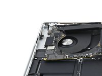
Выберете то, что вам нужно
-
-
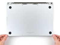
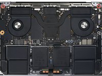
Fully shut down your MacBook, close the lid, and flip it over. Keep the lid closed until you've physically disconnected the battery.
-
Unplug the MagSafe cable and any accessories connected to your MacBook.
-
-
Инструмент, используемый на этом этапе:FixMat$36.95
-
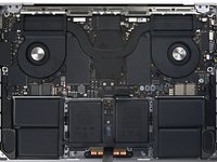
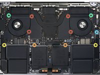
Use a P5 Pentalobe driver to remove eight screws securing the lower case:
-
Four 9.3 mm screws
-
Four 5 mm screws
-
-
-
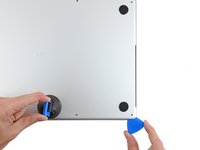
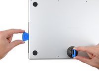
Press a suction handle into place near the front edge of the lower case, between the screw holes.
-
Pull up on the suction handle to create a small gap under the lower case.
-
-
-
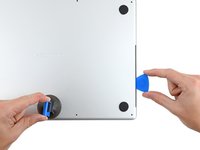
Insert an opening pick into the gap you just created.
-
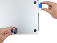
Slide the opening pick around the nearest corner and then halfway up the side of the MacBook Pro.
-
-
-
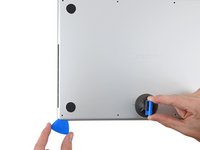
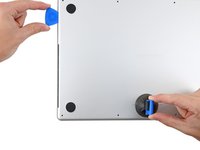
Repeat the previous step on the other side, using an opening pick to to release the second clip.
-
-
-
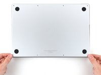
Firmly pull the lower case away from the back edge, one corner at a time, to disengage the sliding clips.
-
-
-
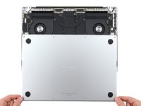
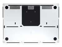
Remove the lower case.
-
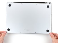
Lay it down and align the sliding clips with the back edge of the MacBook. Press down on the lower case and slide it toward the back edge to engage the clips.
-
Once the back corners of the lower case are secured and flush with the frame, press down along the middle of the lower case to engage the four remaining clips.
-
-
-
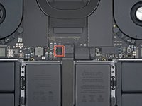
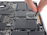
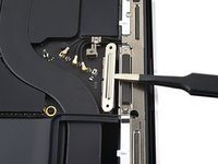
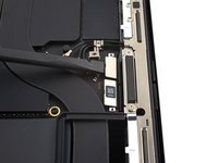
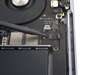
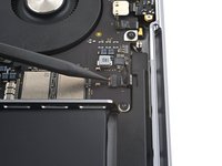
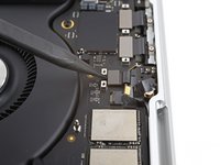
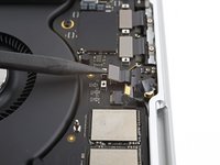
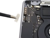
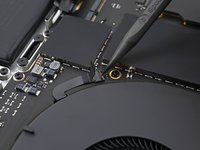
Peel back any tape covering the battery board data cable connector on the logic board.
-
-
-
Use a spudger to gently pry up the locking flap on the ZIF connector for the battery board data cable.
-
-
-
Disconnect the battery board data cable by sliding it out from its socket on the logic board.
-
-
-
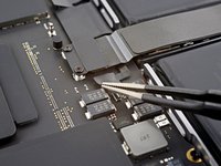
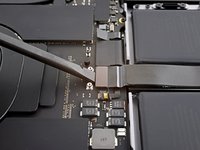
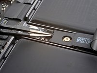
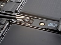
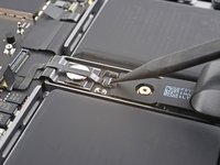
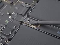
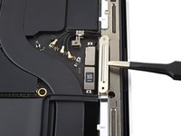
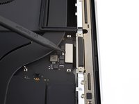
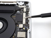
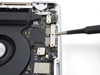
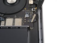
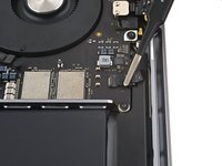
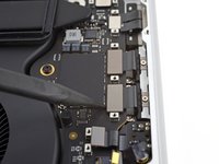
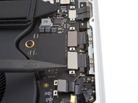
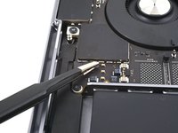
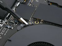
Use a 3IP Torx Plus driver to remove the two 2.1 mm‑long screws securing the trackpad cable bracket to the logic board.
-
-
Инструмент, используемый на этом этапе:Tweezers$4.99
-
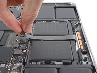
Use tweezers, or your fingers, to remove the trackpad cable bracket.
-
-
-
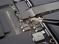
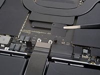
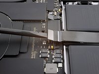
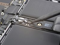
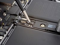
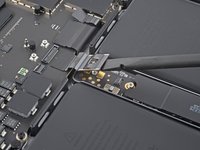
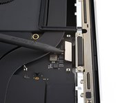
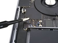
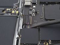
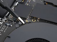
Use the flat end of a spudger to pry up and disconnect the trackpad cable's press connector secured to the logic board.
-
-
-
Peel the trackpad cable away from the device, making sure to separate the adhesive.
-
-
-
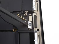
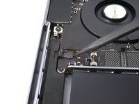
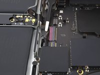
Peel back any tape covering the battery board data cable connector under the large pancake screw.
-
-
-
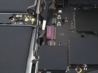
Use a spudger to gently pry up the locking flap on the ZIF connector for the battery board data cable.
-
-
-
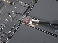
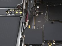
Disconnect the battery board data cable by sliding it out from its socket on the battery board.
-
-
-
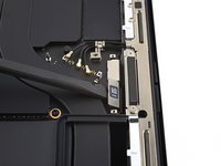
Slide blunt nose tweezers under areas with adhesive to separate the cable from the device.
-
Remove the battery board data cable.
-
-
-
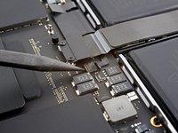
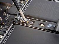
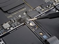
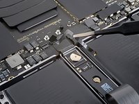
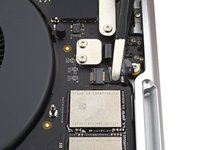
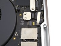
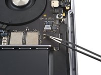
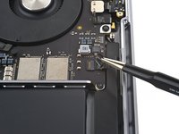
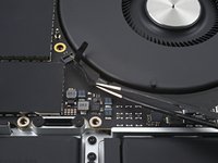
Use a 5IP Torx Plus driver to remove the 3.8 mm wide-head screw securing the battery power connector.
-
-
-
Use the flat end of your spudger to lift the battery connector away from the battery board, disconnecting the battery.
-
-
-
Use a 3IP Torx Plus screwdriver to remove the three 2.1 mm screws securing the antenna board bracket and coaxial cable cover to the frame.
-
-
-
Инструмент, используемый на этом этапе:Tweezers$4.99
-
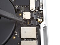
Use tweezers, or your fingers, to remove the cover on top of the antenna bar's coaxial cables.
-
-
-
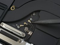
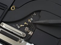
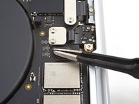
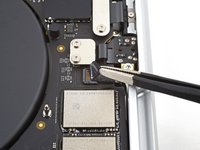
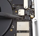
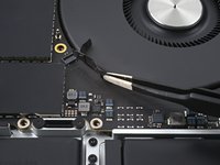
Use the tip of a spudger to pry up and disconnect the antenna bar's coaxial cable.
-
Repeat for the two other cables.
-
-
-
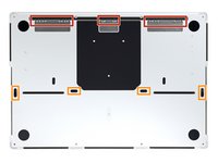
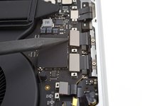
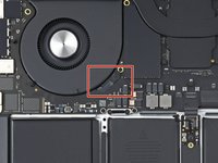
Use a 3IP Torx Plus driver to remove the four 2.1 mm screws securing the screen cable covers.
-
-
-
Use tweezers, or your fingers, to remove the two screen cable covers from the logic board.
-
-
-
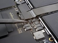
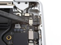
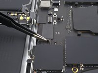
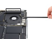
Use the flat end of a spudger to pry up and disconnect the right-most screen cable press connectors secured to the logic board.
-
-
-
Repeat the previous disconnection process for the remaining press connector at the top left of the logic board.
-
-
-
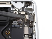
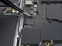
Use a spudger to gently pry up the locking flap on the ZIF connector for the microphone cable.
-
-
-
Disconnect the microphone cable by sliding it out from its socket on the logic board.
-
-
-
Use a 3IP Torx Plus driver to remove the nine 2.1 mm screws securing the right cable covers to the frame:
-
-
-
Use tweezers, or your fingers, to remove the five right cable covers.
-
-
-
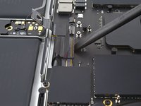
Use a spudger to gently pry up the locking flap on the ZIF connector for the right speaker cable.
-
-
-
Disconnect the right speaker cable by sliding it out from its socket on the logic board.
-
-
-
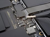
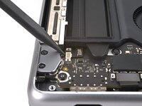
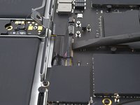
Use a spudger to pry up and disconnect the headphone jack's press connector.
-
-
-
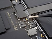
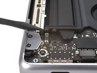
Use a spudger to pry up and disconnect the right USB-C ports' press connectors.
-
-
-
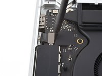
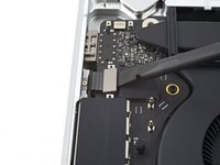
Use a spudger to pry up and disconnect the MagSafe port's press connector.
-
-
-
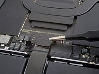
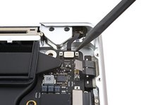
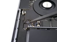
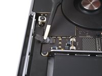
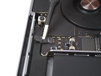
Use a spudger to pry up and disconnect the lid angle sensor's press connector.
-
-
-
Use a 3IP Torx Plus driver to remove the four screws securing the left cable covers to the frame:
-
Two 2 mm screws
-
Two 2.1 mm screw
-
-
-
Use tweezers, or your fingers, to remove the two left cable covers.
-
-
-
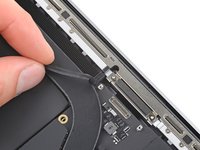
Peel back any tape covering the left speaker cable.
-
-
-
Use a spudger to gently pry up the locking flap on the ZIF connector for the left speaker cable.
-
-
-
Disconnect the left speaker cable by sliding it out from its socket on the logic board.
-
-
-
Use a spudger to pry up and disconnect the left USB-C port's press connector.
-
-
-
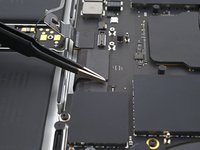
Use a spudger to pry up and disconnect the Touch ID sensor's press connector near the top left of the device.
-
-
-
Peel back any tape covering the keyboard and keyboard backlight cable connectors.
-
-
-
Use a spudger to gently pry up the locking flap on the ZIF connectors for the keyboard cables.
-
-
-
Disconnect the keyboard and keyboard backlight cables by sliding them out from their sockets on the logic board.
-
-
-
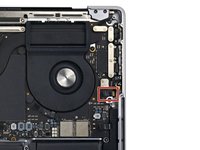
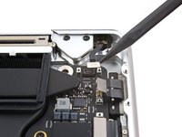
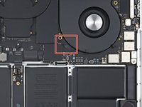
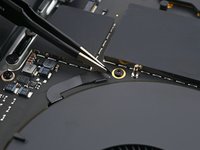
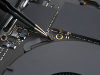
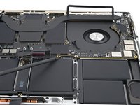
Use a spudger to gently pry up the locking flap on the ZIF connector for the right fan cable.
-
-
-
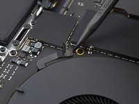
Disconnect the right fan cable by sliding it out from its socket on the logic board.
-
-
-
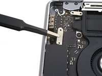
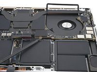
Pull the fan cable away from the logic board with tweezers to separate the adhesive.
-
-
-
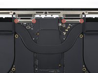
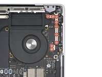
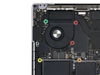
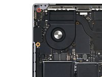
Use a 5IP Torx Plus driver to remove the 11 screws securing the logic board:
-
Four 3.6 mm screws
-
Two 4.5 mm screws
-
Two 5.2 mm screws
-
Two 3.8 mm screws
-
One 3.9 mm screw
-
-
-
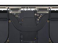
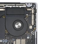
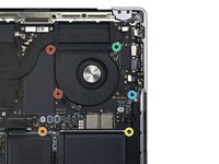
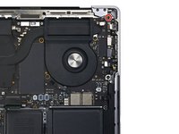
Use a T6 Torx driver to remove the three screws securing the logic board:
-
Two 4.7 mm screws
-
One 5.7 mm screw
-
-
-
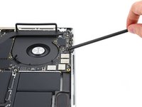
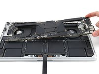
Insert a spudger between the right side of the logic board and the frame.
-
Pry up with the spudger to release the logic board from its clips.
-
-
-
Insert a spudger between the bottom of the logic board and the frame.
-
Pry up with the spudger to release the logic board from its clips.
-
-
-
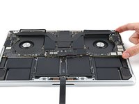
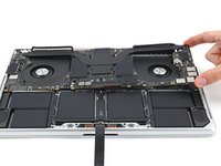
Gently lift up the logic board by its right side to release it from its alignment pegs.
-
Pull the logic board away from the left side of the device to separate the HDMI and SDXC ports from their slots in the frame.
-
Remove the logic board.
-
-
-
Make sure all 18 connectors are above the logic board before securing it back into the frame.
-
Hold the rubber spacers out of the way so the fins can drop into their recesses.
-
When reinstalling the logic board, insert the left side first to reposition the HMDI and SDXC ports.
-
Use your fingers to slightly compress the HDMI port to fit it into its recess. Otherwise, the logic board won't sit correctly.
-


To reassemble your device, follow these instructions in reverse order.
To reassemble your device, follow these instructions in reverse order.

