Введение
The left and right speakers are paired together in the MacBook Pro with Retina display. Therefore, they should be replaced as a pair. Use this guide to help you out with that process.
Выберете то, что вам нужно
-
-
Remove the following P5 pentalobe screws securing the lower case to the MacBook Pro:
-
Eight 3.0 mm
-
Two 2.3 mm
-
-
-
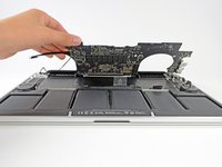
Lifting from the edge nearest the clutch cover, lift the lower case off the MacBook Pro.
-
Set the lower case aside.
-
-
-
Using the flat end of a spudger, gently pry the battery connector straight up out of its socket on the logic board.
-
Bend the battery cables back and out of the way, ensuring that the battery connector doesn't accidentally make contact with the logic board.
-
-
Инструмент, используемый на этом этапе:Tweezers$4.99
-
Use a spudger or tweezers to pry the three AirPort antenna cables straight up off of their sockets on the AirPort board.
-
-
-
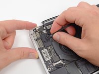
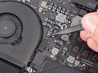
Use the tip of a spudger to push the camera cable's plug toward the fan and out of its socket on the logic board.
-
-
-
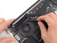
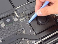
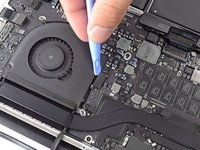
Insert the flat end of a spudger underneath the rubber heat sink cover on the right fan.
-
Slide the spudger underneath the length of the cover, releasing the adhesive.
-
Lift the cover and flip it back so that you can access the cables underneath.
-
-
-
Use your fingers to pull the AirPort/Camera cables up off the fan.
-
Carefully de-route the cables from the plastic cable guide.
-
-
-
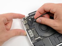
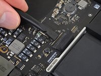
Using the flat end of a spudger, pry the I/O Board connector straight up out of its socket on the logic board.
-
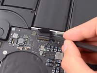
In a similar fashion, remove the I/O Board cable connector from its socket on the I/O Board.
-
Remove the I/O Board cable from the MacBook Pro.
-
-
-
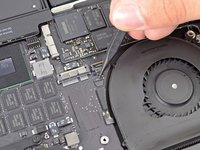
Remove the single 2.9 mm T5 Torx screw securing the AirPort card to the logic board.
-
-
-
Grasp the sides of the AirPort card and lift it up to a shallow angle (5-10˚) to separate the light adhesive adhering it to the logic board.
-
Pull the AirPort card parallel out of its connector on the logic board to remove it.
-
-
-
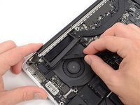
Use the tip of a spudger to flip up the retaining flap on the right fan ribbon cable ZIF socket.
-
Starting at the top of the cable, slide a plastic opening tool under the right fan cable to free it from the logic board.
-
-
-
-
Remove the following three screws securing the right fan to the logic board:
-
One 4.4 mm T5 Torx screw
-
One 3.9 mm T5 Wide Head Torx screw
-
One 5.0 mm T5 Torx screw with 2 mm collar
-
-
-
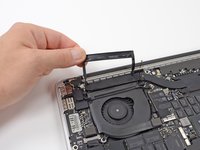
Use the flat end of a spudger to lift the rubber heat sink cover up off the left fan.
-
-
-
Remove the following three screws securing the left fan to the logic board:
-
One 4.4 mm T5 Torx screw with 2 mm collar
-
One 5.0 mm T5 Torx screw with 2 mm collar
-
One 3.9 mm T5 Wide Head Torx screw
-
-
-
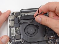
Use the tip of a spudger to flip up the retaining flap on the left fan ribbon cable ZIF socket.
-
Starting at the top of the cable, slide a plastic opening tool under the left fan cable to free it from the logic board.
-
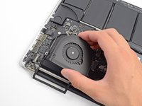
Lift the left fan out of the device.
-
-
-
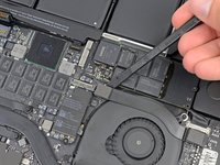
Remove the single 3.1 mm T5 Torx screw securing the SSD to the logic board.
-
-
-
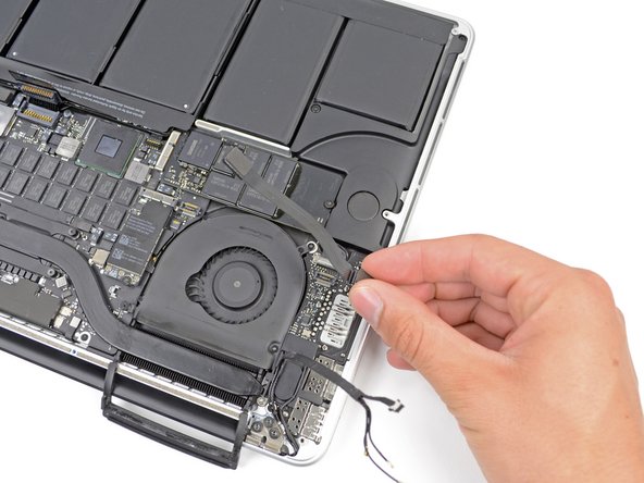
Slightly lift the rightmost side of the SSD and firmly slide it straight away out of its socket on the logic board.
-
-
-
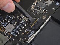
Use the tip of a spudger to flip up the I/O board data cable lock and rotate it toward the battery side of the computer.
-
Use the flat end of a spudger to slide the I/O board data cable straight out of its socket on the logic board.
-
-
-
Remove the two 3.1 mm T5 Torx screws securing the I/O board to the logic board.
-
On some models, also removing the silver 3.5 mm T5 Torx screw from the heatsink can aid in I/O board removal.
-
Carefully lift the I/O board and remove it from the lower case.
-
-
-
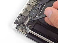
Use the flat end of a spudger to pry the headphone jack connector up from its socket on the logic board.
-
-
-
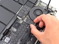
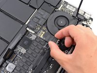
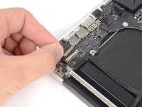
Use the flat end of a spudger to pry the left speaker connector up and out of its socket on the logic board.
-
Use the tip of a spudger to pry the right speaker connector up and out of its socket on the logic board
-
-
-
Use the flat end of a spudger to flip up the retaining flap on the keyboard ribbon cable ZIF socket.
-
Use the flat end of a spudger to gently back the keyboard ribbon cable out of its socket by pushing first at one side, then the other.
-
-
-
Use the flat end of a spudger to pry the trackpad ribbon cable connector up from its socket on the logic board.
-
-
-
Use the flat end of a spudger to pry the keyboard backlight connector up from its socket on the logic board.
-
-
-
Use the tip of a spudger or your fingernail to flip up the retaining flap on the microphone ribbon cable ZIF socket.
-
Pull the microphone ribbon cable out of its socket.
-
-
-
Use the tip of a spudger to pry the display data cable lock and rotate it toward the DC-In side of the computer.
-
Pull the display data cable straight out of its socket on the logic board.
-
-
-
Use the flat end of a spudger to carefully pry off the rubber screw cap on the raised screw head near to the MagSafe 2 connector.
-
-
-
Remove the following six screws securing the logic board to to the upper case:
-
One 2.6 mm T5 Torx screw
-
Two 5.8 mm T5 Torx screws
-
One 3.8 mm T5 Torx screw
-
One 5.2 mm Raised Head T5 Torx screw
-
One 3.5 mm Silver T5 Torx screw
-
-
-
Lifting from the side nearest the battery, rotate the logic board toward the top of the MacBook Pro.
-
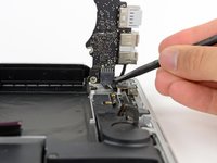
Using the flat end of a spudger, carefully push the MagSafe 2 connector out of its socket on the bottom of the logic board.
-
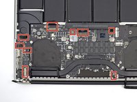
Clockwise from top: keyboard, trackpad, battery, right speaker, keyboard backlight, display, microphone, headphone jack, left speaker.
-
-
-
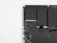
Remove the following three screws securing the left speaker to the upper case:
-
One 5.6 mm T5 Torx screw
-
One 6.9 mm T5 Torx screw
-
One 2.6 mm T5 Torx screw
-
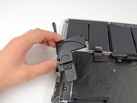
Lift the left speaker out of the upper case and set it aside.
-
-
-
Remove the following three screws securing the right speaker to the upper case:
-
One 5.6 mm T5 Torx screw
-
One 6.9 mm T5 Torx screw
-
One 2.6 mm T5 Torx screw
-
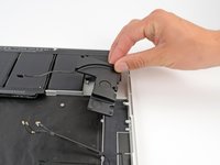
Remove the right speaker from the MacBook Pro.
-


To reassemble your device, follow these instructions in reverse order.
To reassemble your device, follow these instructions in reverse order.
Отменить: Я не выполнил это руководство.
90 человек успешно провели ремонт по этому руководству.


18 Комментариев
Am I required to change both speakers if only one is damaged? The top of the guide explains it should be replaced as a pair... Don't see why it would be required? Thanks
I have the same question - clearly one speaker is buzzing while the other sounds fine. Why replace both?
Andrew -
Speakers are frequently tested for frequency response and impedance and ones that are similar are paired with one another for installation as a matched set. I presume this is the reasoning behind the statement at the top of this guide.
Why is there a need for the speakers to "be replaced as a pair" as noted in the introduction, why can't just one be replaced? or was this not the intention of the author when he wrote that sentence?