Введение
Use this guide to replace a faulty logic board.
Выберете то, что вам нужно
-
-
Remove the following ten screws securing the lower case to the upper case:
-
Seven 3 mm Phillips screws.
-
Three 13.5 mm Phillips screws.
-
-
-
Using both hands, lift the lower case near the vent to pop it off two clips securing it to the upper case.
-
Remove the lower case and set it aside.
-
-
КупитьИнструмент, используемый на этом этапе:P6 Pentalobe Screwdriver 2009 15" MacBook Pro Battery$5.49
-
Three Pentalobe screws secure the battery to the upper case. They can be removed with this special driver.
-
-
-
Remove the two exposed five-point Pentalobe screws along the top edge of the battery.
-
-
-
Use the tip of a spudger to bend back the finger of the "Warning: Do not remove the battery" sticker while you remove the five-point Pentalobe screw hidden underneath.
-
-
-
Lift the battery by its plastic pull tab and slide it away from the long edge of the upper case.
-
-
-
Tilt the battery back enough to access the battery cable connector.
-
Pull the battery cable connector away from its socket on the logic board and remove the battery from the upper case.
-
-
-
Use the flat end of a spudger to pry the fan cable connector up off its socket on the logic board.
-
-
-
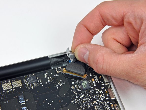
Hold the end of the cable retainer down with one finger while you use the tip of a spudger to slightly lift the other end and rotate it away from the camera cable connector.
-
-
-
-
Disconnect the camera cable by pulling the male end straight away from its socket.
-
-
-
Use the flat end of a spudger to pry the optical drive cable connector up off the logic board.
-
-
-
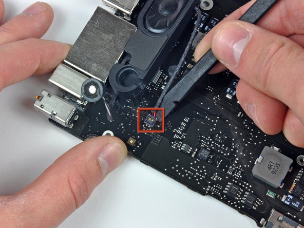
Using the flat end of a spudger, pry the subwoofer connector straight up off the logic board.
-
-
-
Use the flat end of a spudger to pry the hard drive/IR sensor cable connector up off the logic board.
-
-
-
Remove the two 1.5 mm Phillips screws securing the cable cover to the logic board.
-
Lift the cable cover out of the upper case.
-
-
-
Use a spudger to pry the trackpad flex ribbon cable connector up off the logic board.
-
-
-
Using the tip of a spudger, flip up the keyboard ribbon cable retaining flap.
-
Pull the keyboard ribbon cable straight out of its socket.
-
-
-
Use a spudger to pry the battery indicator ribbon cable connector up off the logic board.
-
-
-
Remove the single 7 mm Phillips screw securing the display data cable retainer to the upper case.
-
Remove the display data cable retainer from the upper case.
-
-
-
Grab the plastic pull tab secured to the display data cable lock and rotate it toward the DC-in side of the computer.
-
Pull the display data cable connector straight away from its socket.
-
-
-
Using the tip of a spudger, flip up the keyboard backlight ribbon cable retaining flap.
-
Pull the keyboard backlight ribbon cable straight out of its socket.
-
-
-
Remove the following screws:
-
Eight 3.5 mm T6 Torx screws securing the logic board to the upper case.
-
Two T6 Torx screws securing the DC-In board to the upper case.
-
-
-
Carefully lift the logic board assembly from the left side and work it out of the upper case, minding the port side that may get caught during removal.
-
-
-
Lift the logic board enough to gain clearance and use a spudger to pry the microphone up off the upper case.
-
Slide the logic board away from the port openings and lift the assembly out of the upper case.
-
-
-
Remove six Phillips screws securing the heat sink to the logic board.
-
-
-
Disconnect the DC-In Board connector from the logic board by pulling it straight away from its socket.
-
-
-
Remove the two 5 mm Phillips screws securing the left speaker to the logic board assembly.
-
-
-
Use the flat end of a spudger to pry the left speaker connector up off the logic board.
-
-
-
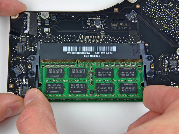
Release the tabs on each side of the RAM chip by simultaneously pushing each tab away from the chip.
-
After the RAM chip has popped up, pull it straight out of its socket.
-


To reassemble your device, follow these instructions in reverse order.
To reassemble your device, follow these instructions in reverse order.
Отменить: Я не выполнил это руководство.
30 участников успешно повторили данное руководство.

4 Комментариев
Hello,
Do you know the purpose of the component that is not welded in the lower right corner of the red square on the picture of step 12: http://d3nevzfk7ii3be.cloudfront.net/igi...
Someone tells me I can not have my backlight re-working without this component, but I think it simply does not work because of a liquid.
Any ideas ?
Thanks in advance
I just replaced the logic board, and all went fine, as far as I can tell. However, my new battery is still in transit, i.e: I do not have it at hand. My question is, how critical is it to have a battery in this model....given all the "do not remove battery or else" warnings. Is it OK to try to boot it just with the regular power supply? I do not want to fry my new logic board, so I need some informed opinion on this...
I greatly appreciated your comment in Step 11 saying: “Apple sticks a small strip of clear plastic with adhesive applied to one side to the logic board behind the camera cable connector to keep it in its socket“.
My problem was that I had an old Macbook Pro whose camera cable was out of its socket and I could not get it in because this piece of plastic was in the way. I had no idea what it was. It was not clear to me if it was an IC or some other important component. Your comment clarified what it was and its purpose.
Pushing down on it at one end did not achieve anything, so I have just lifted it up and off the board using a small scalpel blade.
I will use some tape to hold the cable connector in its socket.
Thank you
Hi,
Your article does not mention the WiFi (wireless) or Bluetooth cable connector.
Does WiFi connectivity come into the logic board via the camera cable, or some other cable?
Thank you