Эта версия возможно содержит некорректные исправления. Переключить на последнюю проверенную версию.
Выберете то, что вам нужно
-
Этот шаг не переведен. Помогите перевести
-
With the case closed, place the Unibody top-side down on a flat surface.
-
Depress the grooved side of the access door release latch enough to grab the free end. Lift the release latch until it is vertical.
-
-
Этот шаг не переведен. Помогите перевести
-
The access door should now be raised enough to lift it up and out of the Unibody.
-
-
Этот шаг не переведен. Помогите перевести
-
Grab the translucent plastic tab and pull the battery up and out of the Unibody.
-
If the latch is depressed it will lock the battery in place.
-
-
Этот шаг не переведен. Помогите перевести
-
Remove the following eight screws securing the lower case to the chassis:
-
One 5.4 mm Phillips screw.
-
Three 14 mm Phillips screws.
-
Four 3.5 mm Phillips screws.
-
-
Этот шаг не переведен. Помогите перевести
-
Using both hands, lift and remove the lower case off the upper case.
-
-
Этот шаг не переведен. Помогите перевести
-
Disconnect the camera cable by pulling the male end straight away from its socket.
-
-
Этот шаг не переведен. Помогите перевести
-
Deroute the camera data cable from the channel in the optical drive.
-
-
-
Этот шаг не переведен. Помогите перевести
-
Use a spudger to pry the optical drive connector straight up off the logic board.
-
-
Этот шаг не переведен. Помогите перевести
-
Remove two 8 mm Phillips screws securing the camera cable bracket to the upper case.
-
Lift the camera cable bracket out from the upper case.
-
-
Этот шаг не переведен. Помогите перевести
-
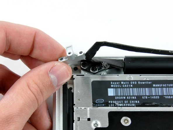
Remove the following three Phillips screws securing the optical drive to the upper case:
-
One 3.5 mm Phillips screw.
-
Two 2.5 mm Phillips screws.
-
-
Этот шаг не переведен. Помогите перевести
-
Lift the optical drive from its left edge and pull it out of the computer.
-
-
Этот шаг не переведен. Помогите перевести
-
Using the flat end of a spudger, pry the subwoofer connector straight up off the logic board.
-
-
Этот шаг не переведен. Помогите перевести
-
Remove the following four screws securing the subwoofer and right speaker to the upper case:
-
Two 3.2 mm Phillips screws.
-
One 2.6 mm Phillips screw.
-
One 5 mm Phillips screw.
-
-
Этот шаг не переведен. Помогите перевести
-
Lift the subwoofer and right speaker assembly out of the upper case.
-
-
Этот шаг не переведен. Помогите перевести
-
Remove the single Phillips screw securing the hard drive bracket to the upper case.
-
-
Этот шаг не переведен. Помогите перевести
-
Lift the hard drive by its plastic pull tab and remove the freed hard drive bracket.
-
-
Этот шаг не переведен. Помогите перевести
-
Lift the hard drive out of its supports and disconnect the SATA cable by pulling the connector straight away from the hard drive.
-
-
Этот шаг не переведен. Помогите перевести
-
Remove the following 5 screws securing the mid wall to the upper case:
-
Three 10.5 mm Phillips screws.
-
Two 3.7 mm Phillips screws.
-
Lift the mid wall out of the upper case.
-
-
Этот шаг не переведен. Помогите перевести
-
Use a spudger to pry the hard drive cable connector straight up off the logic board.
-
-
Этот шаг не переведен. Помогите перевести
-
Peel the hard drive cable from the adhesive securing it to the upper case, and maneuver the plastic retaining block out of the upper case.
-


Отменить: Я не выполнил это руководство.
9 участников успешно повторили данное руководство.

Один комментарий
great explanation I was looking for instruction on YouTube but with no luck thank you so much !!!