Введение
The hard drive cable also contains the IR sensor/sleep indicator.
Выберете то, что вам нужно
-
-
Remove the following ten screws securing the lower case to the upper case:
-
Three 13.5 mm (14.1 mm) Phillips screws.
-
Seven 3 mm Phillips screws.
-
-
-
Using both hands, lift the lower case near the vent to pop it off two clips securing it to the upper case.
-
Remove the lower case and set it aside.
-
-
-
Use the edge of a spudger to pry the battery connector upwards from its socket on the logic board.
-
-
-
Bend the battery cable slightly away from its socket on the logic board so it does not accidentally connect itself while you work.
-
-
-
-
Remove two Phillips screws securing the hard drive bracket to the upper case.
-
-
-
Lift the hard drive by its pull tab and pull it out of the chassis, minding the cable attaching it to the computer.
-
-
-
Remove the hard drive cable by pulling its connector straight away from the hard drive.
-
-
-
Use the flat end of a spudger to pry the hard drive cable connector up off the logic board.
-
-
-
Remove the following four screws securing the hard drive and IR sensor cable to the upper case:
-
Two 1.5 mm Phillips screws.
-
Two 4 mm Phillips screws.
-
-
-
Slide the hard drive and IR sensor bracket away from the edge of the upper case.
-
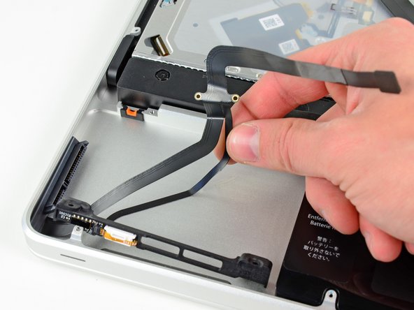
Carefully peel the hard drive and IR sensor cable from the upper case.
-
Lift the hard drive and IR sensor assembly out of the upper case.
-
-
-
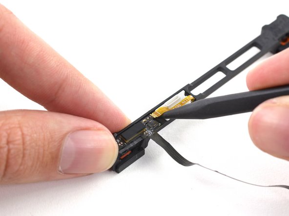
Use the tip of a spudger to flip the ZIF connector on the hard drive cable.
-
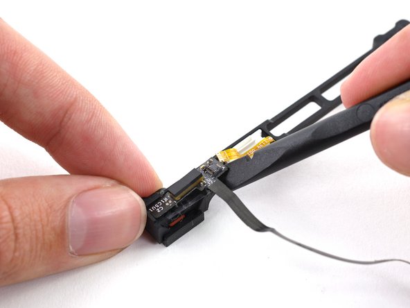
Gently pull the sensor bracket cable out of the ZIF connector.
-
Use the flat end of a spudger to pry the hard drive cable up off the sensor bracket.
-


To reassemble your device, follow these instructions in reverse order.
To reassemble your device, follow these instructions in reverse order.
Отменить: Я не выполнил это руководство.
14 участников успешно повторили данное руководство.

3 Комментариев
Followed these instructions and completed the changeover, probably took half hour. The final step with the ZIF connector I was unable to see exactly how it worked but managed with a bit of trial and error and things are now working. Perhaps a closer photo or perhaps a diagram as to how the connector works? But all in all things worked. Thanks
Is there any way to fix failed graphics card on MacBook Pro 2011. At this stage it’s looking like I have to trash the thing?