Эта версия возможно содержит некорректные исправления. Переключить на последнюю проверенную версию.
Выберете то, что вам нужно
-
Этот шаг не переведен. Помогите перевести
-
Remove the following ten screws securing the lower case to the upper case:
-
Three 13.5 mm (14.1 mm) Phillips screws.
-
Seven 3 mm Phillips screws.
-
-
Этот шаг не переведен. Помогите перевести
-
Using both hands, lift the lower case near the vent to pop it off two clips securing it to the upper case.
-
Remove the lower case and set it aside.
-
-
Этот шаг не переведен. Помогите перевести
-
Use the edge of a spudger to pry the battery connector upwards from its socket on the logic board.
-
-
Этот шаг не переведен. Помогите перевести
-
Bend the battery cable slightly away from its socket on the logic board so it does not accidentally connect itself while you work.
-
-
Этот шаг не переведен. Помогите перевести
-
Remove the three 3.4 mm T6 Torx screws securing the left fan to the logic board.
-
-
Этот шаг не переведен. Помогите перевести
-
Use the flat end of a spudger to disconnect the left fan connector from the logic board.
-
-
Этот шаг не переведен. Помогите перевести
-
Use the flat end of a spudger to lift the right fan connector out of its socket on the logic board.
-
-
-
Этот шаг не переведен. Помогите перевести
-
Remove the three 3.4 mm (3.1 mm) T6 Torx screws securing the right fan to the logic board.
-
Lift the right fan out of its opening in the logic board.
-
-
Этот шаг не переведен. Помогите перевести
-
Pull the camera cable out of its socket on the logic board.
-
-
Этот шаг не переведен. Помогите перевести
-
Use the flat end of a spudger to pry the AirPort/Bluetooth connector up from its socket on the logic board.
-
-
Этот шаг не переведен. Помогите перевести
-
Use the flat end of a spudger to lift the optical drive connector out of its socket on the logic board.
-
-
Этот шаг не переведен. Помогите перевести
-
Disconnect the hard drive/IR sensor cable from its socket on the logic board by lifting up from beneath its connector.
-
-
Этот шаг не переведен. Помогите перевести
-
Use the flat end of a spudger to lift the subwoofer/right speaker connector out of its socket on the logic board.
-
-
Этот шаг не переведен. Помогите перевести
-
Remove the two 1.5 mm ( 1.2 mm ) Phillips screws securing the keyboard/trackpad cable cover to the logic board.
-
Lift the cover off the logic board and set it aside.
-
-
Этот шаг не переведен. Помогите перевести
-
Use the flat end of a spudger to pry the trackpad connector up and out of its socket on the logic board.
-
-
Этот шаг не переведен. Помогите перевести
-
Use your fingernail to flip up the retaining flap on the keyboard ribbon cable ZIF socket.
-
Use the tip of a spudger to pull the keyboard ribbon cable out of its socket.
-
-
Этот шаг не переведен. Помогите перевести
-
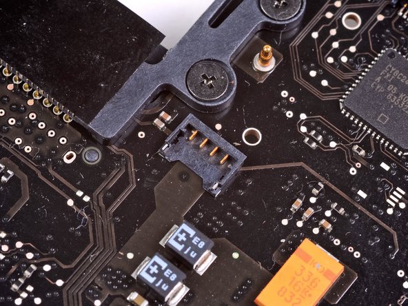
Use the flat end of a spudger to lift the battery indicator connector up and out of its socket on the logic board.
-
-
Этот шаг не переведен. Помогите перевести
-
Grab the plastic pull tab secured to the display data cable lock and rotate it toward the DC-In side of the computer.
-
Pull the display data cable straight out of its socket on the logic board.
-
-
Этот шаг не переведен. Помогите перевести
-
Use the tip of a spudger to flip up the retaining flap on the keyboard backlight ribbon cable ZIF socket.
-
Pull the keyboard backlight ribbon cable out of its socket.
-
-
Этот шаг не переведен. Помогите перевести
-
Remove the following nine screws:
-
Seven 3.4 mm ( 3.1 mm) T6 Torx screws on the logic board
-
Two 8 mm T6 Torx screws on the DC-In board
-
-
Этот шаг не переведен. Помогите перевести
-
Carefully lift the logic board assembly from its left side and work it out of the upper case, minding the optical drive cable and the I/O ports that may get caught during removal.
-
If necessary, use the flat end of a spudger to separate the microphone from the upper case.
-
Pull the I/O port side of the logic board away from the side of the upper case and remove the logic board assembly.
-
-
Этот шаг не переведен. Помогите перевести
-
Disconnect the DC-In board by pulling its cable toward the heat sink.
-


Отменить: Я не выполнил это руководство.
34 участников успешно повторили данное руководство.

2 Комментариев
for mee too
can you please post an guide too repair that ?