Введение
Has your MacBook Pro lost its magic touch? Bring it back with a new trackpad.
Выберете то, что вам нужно
-
-
Remove the following ten screws securing the lower case to the upper case:
-
Three 13.5 mm (14.1 mm) Phillips screws.
-
Seven 3 mm Phillips screws.
-
-
-
Using both hands, lift the lower case near the vent to pop it off two clips securing it to the upper case.
-
Remove the lower case and set it aside.
-
-
-
Use the edge of a spudger to pry the battery connector upwards from its socket on the logic board.
-
-
-
Bend the battery cable slightly away from its socket on the logic board so it does not accidentally connect itself while you work.
-
-
-
Remove the following three screws securing the left fan to the logic board:
-
Two 3.5 mm T6 Torx screws.
-
One 4.2 mm T6 Torx screw.
-
-
-
Use the flat end of a spudger to disconnect the left fan connector from the logic board.
-
-
-
Use the flat end of a spudger to lift the right fan connector out of its socket on the logic board.
-
-
-
Remove the three 3.4 mm (3.1 mm) T6 Torx screws securing the right fan to the logic board.
-
Lift the right fan out of its opening in the logic board.
-
-
-
-
Use the flat end of a spudger to pry the AirPort/Bluetooth connector up from its socket on the logic board.
-
-
-
Use the flat end of a spudger to lift the optical drive connector out of its socket on the logic board.
-
-
-
Disconnect the hard drive/IR sensor cable from its socket on the logic board by lifting up from beneath its connector.
-
-
-
Use the flat end of a spudger to lift the subwoofer/right speaker connector out of its socket on the logic board.
-
-
-
Remove the two 1.5 mm ( 1.2 mm ) Phillips screws securing the keyboard/trackpad cable cover to the logic board.
-
Lift the cover off the logic board and set it aside.
-
-
-
Use the flat end of a spudger to pry the trackpad connector up and out of its socket on the logic board.
-
-
-
Use your fingernail to flip up the retaining flap on the keyboard ribbon cable ZIF socket.
-
Use the tip of a spudger to pull the keyboard ribbon cable out of its socket.
-
-
-
Use the flat end of a spudger to lift the battery indicator connector up and out of its socket on the logic board.
-
-
-
Grab the plastic pull tab secured to the display data cable lock and rotate it toward the DC-In side of the computer.
-
Pull the display data cable straight out of its socket on the logic board.
-
-
-
Use the tip of a spudger to flip up the retaining flap on the keyboard backlight ribbon cable ZIF socket.
-
Pull the keyboard backlight ribbon cable out of its socket.
-
-
-
Remove the following nine screws:
-
Seven 3.4 mm ( 3.1 mm) T6 Torx screws on the logic board
-
Two 8 mm T6 Torx screws on the DC-In board
-
-
-
Carefully lift the logic board assembly from its left side and work it out of the upper case, minding the optical drive cable and the I/O ports that may get caught during removal.
-
If necessary, use the flat end of a spudger to separate the microphone from the upper case.
-
Pull the I/O port side of the logic board away from the side of the upper case and remove the logic board assembly.
-
-
-
Remove the two 7.5 mm ( 7.2 mm )Tri-point screws securing the battery to the upper case.
-
-
-
Carefully peel the battery warning label off the upper case between the battery and the optical drive to reveal an additional Tri-point screw.
-
Remove the last 7.5 mm ( 7.2 mm ) Tri-point screw securing the battery to the upper case.
-
-
-
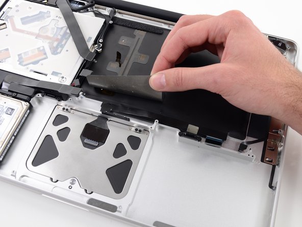
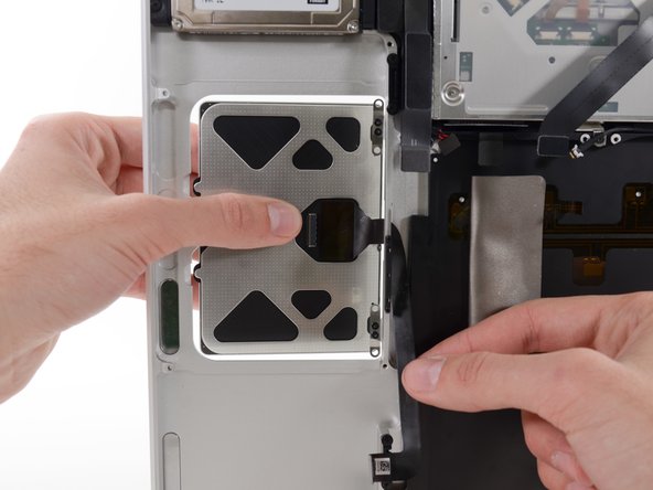
Use the flat end of a spudger to peel up the edge of the large piece of black tape covering the trackpad cable.
-
Peel the tape up and fold it back out of the way of the trackpad cable. Leaving it in place on the upper case will make it easier to reapply it during reassembly.
-
-
-
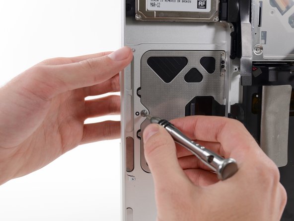
Remove the four silver 1.3 mm Phillips #00 screws from the trackpad spring brackets.
-
-
-
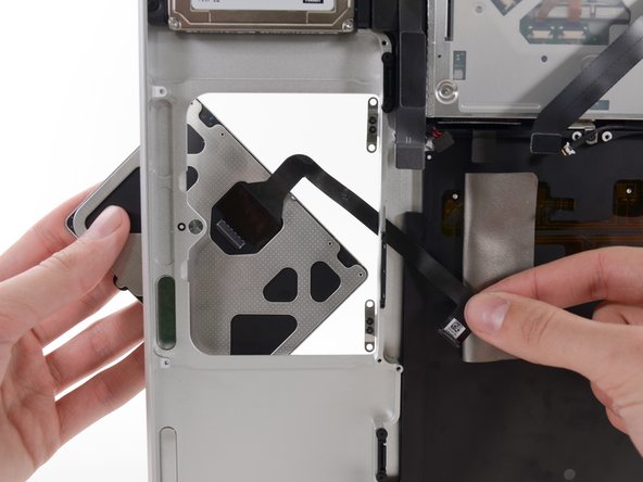
Once the trackpad is free of the upper case, guide the ribbon cable through the slot cut in the upper case.
-
-
-
When reinstalling the trackpad, loosely replace the four Phillips screws and check the alignment of the trackpad on the keyboard side of the upper case.
-
Once you have centered the trackpad in the upper case, tighten the Phillips screws all the way.
-
Use the large Tri-point screw at the bottom of the trackpad to adjust the click stroke.
-


To reassemble your device, follow these instructions in reverse order.
To reassemble your device, follow these instructions in reverse order.
Отменить: Я не выполнил это руководство.
37 участников успешно повторили данное руководство.
