Эта версия возможно содержит некорректные исправления. Переключить на последнюю проверенную версию.
Выберете то, что вам нужно
-
Этот шаг не переведен. Помогите перевести
-
Use your fingers to push both battery release tabs away from the battery and lift the battery out of the computer.
-
-
Этот шаг не переведен. Помогите перевести
-
Remove the four identical Phillips 3.4 mm screws from the memory door. These screws have 4 mm diameter heads rather than the 3 mm heads on the body screws.
-
-
Этот шаг не переведен. Помогите перевести
-
Lift the memory door up enough to get a grip on it, and slide it toward you, pulling it away from the casing.
-
-
Этот шаг не переведен. Помогите перевести
-
Remove the three Phillips screws in the battery compartment near the latch. Apple was nice enough to tilt these screws at a slight angle to make them easier to remove. On the A1261 these screws have 4 mm diameter heads rather than the 3 mm heads on the body screws.
-
-
Этот шаг не переведен. Помогите перевести
-
Remove the following six screws:
-
Two 14.5 mm T6 Torx screws on either side of the RAM slot.
-
Four 3.4 mm Phillips screws along the hinge.
-
-
Этот шаг не переведен. Помогите перевести
-
Remove the four 3.4 mm Phillips screws on the port side of the computer.
-
-
Этот шаг не переведен. Помогите перевести
-
Rotate the computer 90 degrees and remove the two Phillips screws from the rear of the computer.
-
-
Этот шаг не переведен. Помогите перевести
-
Rotate the computer 90 degrees again and remove the four Phillips screws from the side of the computer.
-
-
Этот шаг не переведен. Помогите перевести
-
Lift up the back of the case and work your fingers along the sides, freeing the case as you go. Once you have freed the sides, you may need to rock the case up and down to free the front of the upper case.
-
-
Этот шаг не переведен. Помогите перевести
-
Disconnect the trackpad and keyboard ribbon cable from the logic board.
-
Remove the upper case.
-
-
Этот шаг не переведен. Помогите перевести
-
Disconnect the two antenna cables from the AirPort Extreme card, the iSight and inverter cables from the left side of the logic board, and the display data cable from the right side of the logic board. Be careful to slide the connectors as they may become damaged otherwise.
-
Carefully peel the iSight and inverter cables off the top of the left fan and de-route the AirPort antenna cables from the channel in the left speaker.
-
-
Этот шаг не переведен. Помогите перевести
-
Remove the ten silver T6 Torx screws securing the display (five on each side-take note that the inside screws on both sides are longer with a thinner head).
-
-
-
Этот шаг не переведен. Помогите перевести
-
Grasp the display assembly on both sides and lift it up and out of the computer.
-
-
Этот шаг не переведен. Помогите перевести
-
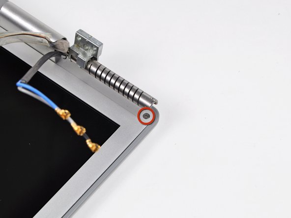
Remove the Phillips screws from the lower left and right corners of the display (two screws total).
-
-
Этот шаг не переведен. Помогите перевести
-
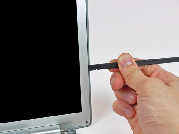
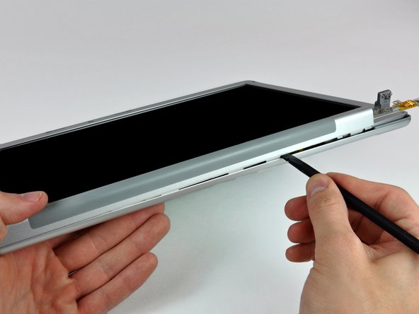
Insert the flat end of a spudger perpendicular to the face of the display between the plastic strip attached to the rear bezel and the front bezel.
-
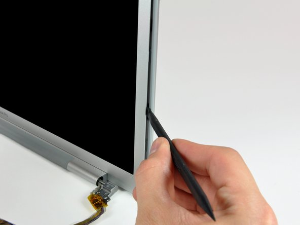
With the spudger still inserted, rotate it away from the display to separate the front and rear bezels.
-
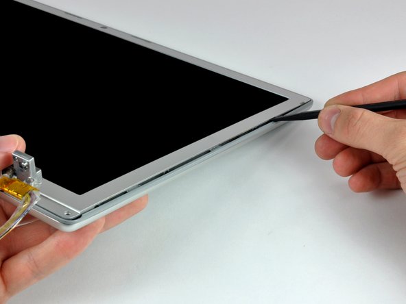
Work along the right edge of the display until the rear bezel is evenly separated from the front bezel.
-
-
Этот шаг не переведен. Помогите перевести
-
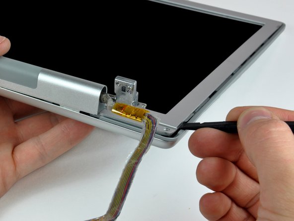
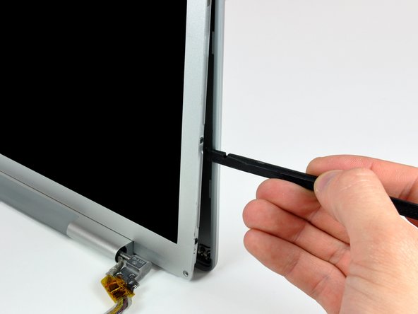
Insert your spudger between the front and rear display bezels at the lower right corner of the display.
-
Pry the rear bezel away from the front bezel to slightly separate the bottom edge of the rear display bezel.
-
-
Этот шаг не переведен. Помогите перевести
-
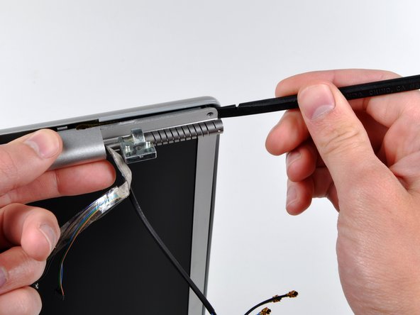
Insert the flat end of a spudger into the gap between the rear display bezel and the clutch cover.
-
Twist the spudger to separate the lower edge of the rear display bezel from the clutch cover.
-
Work along the lower edge of the rear bezel until it is evenly separated from the clutch cover.
-
-
Этот шаг не переведен. Помогите перевести
-
Now that the right and bottom edges of the rear bezel are slightly separated from the front bezel, use a spudger to pop the rear bezel off the tabs near the lower right corner of the display.
-
-
Этот шаг не переведен. Помогите перевести
-
Insert the flat end of a spudger between the front bezel and the plastic strip attached to the rear bezel near the screw holes at the bottom corners of the display.
-
Rotate your spudger toward the rear bezel to separate it from the front bezel.
-
-
Этот шаг не переведен. Помогите перевести
-
Slightly lift the lower edge of the display and pull it away from the rear display bezel.
-
The rear display bezel remains.
-
-
Этот шаг не переведен. Помогите перевести
-
Remove the piece of tape securing the backlight cables to the front display bezel.
-
-
Этот шаг не переведен. Помогите перевести
-
Disconnect the inverter cable by pulling its connector away from the socket on the inverter board.
-
-
Этот шаг не переведен. Помогите перевести
-
Disconnect the backlight connector from the inverter board.
-
Remove the inverter from the display.
-
-
Этот шаг не переведен. Помогите перевести
-
Use the flat end of a spudger to carefully peel off the three antenna straps stuck to the lower edge of the LCD.
-
-
Этот шаг не переведен. Помогите перевести
-
Remove the five Phillips screws securing the clutch cover to the bottom edge of the front display bezel.
-
-
Этот шаг не переведен. Помогите перевести
-
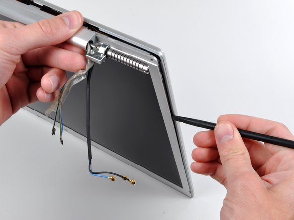
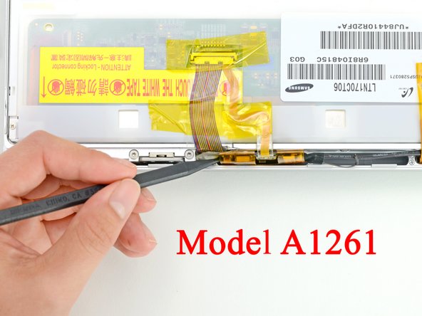
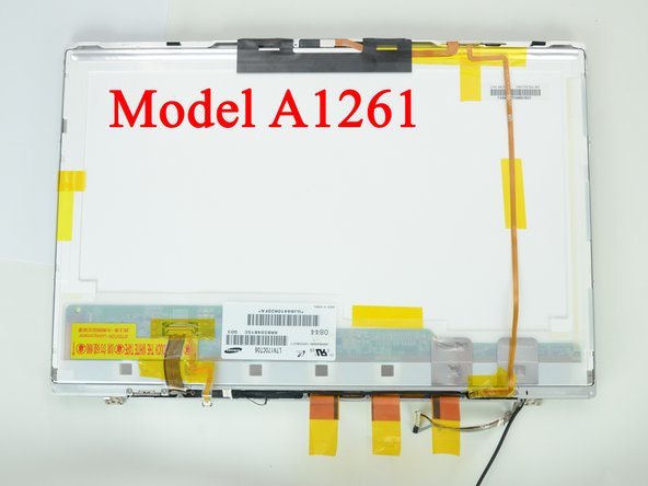
Remove the two pieces of tape securing the display data cable to the LCD.
-
-
Этот шаг не переведен. Помогите перевести
-
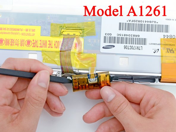
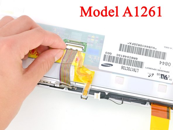
Disconnect the display data cable from the LCD by pulling it toward the bottom edge of the display.
-
-
Этот шаг не переведен. Помогите перевести
-
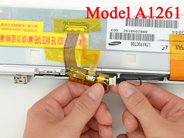
Move the display data cable out of the way to remove the Phillips screw hidden underneath.
-
-
Этот шаг не переведен. Помогите перевести
-
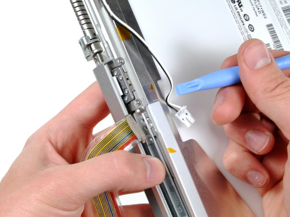
While pulling the clutch assembly away from the clutch hinge with one hand, insert an iPod opening tool between the clutch cover and the front display bezel to lift the clutch cover over the retaining pin on the front display bezel.
-
Pull the clutch assembly away from the front display bezel.
-
-
Этот шаг не переведен. Помогите перевести
-
Repeat the process covered in the previous step to free the other side of the clutch assembly from the front display bezel.
-
-
Этот шаг не переведен. Помогите перевести
-
Remove the clutch assembly from the front display bezel, minding any cables that may get caught.
-
-
Этот шаг не переведен. Помогите перевести
-
Remove the five small Phillips screws securing the plastic antenna cover to the inside of the clutch cover.
-
-
Этот шаг не переведен. Помогите перевести
-
Pull the antenna cover off the clutch cover, being careful not to damage the antenna cables.
-
-
Этот шаг не переведен. Помогите перевести
-
If necessary, peel the antenna leads off the adhesive securing them to the clutch cover.
-
-
Этот шаг не переведен. Помогите перевести
-
Remove the antenna cables from the clutch cover, being careful not to damage the three antenna straps.
-


Отменить: Я не выполнил это руководство.
4 участников успешно повторили данное руководство.
