Эта версия возможно содержит некорректные исправления. Переключить на последнюю проверенную версию.
Выберете то, что вам нужно
-
Этот шаг не переведен. Помогите перевести
-
With the case closed, place the Unibody top-side down on a flat surface.
-
Depress the grooved side of the access door release latch enough to grab the free end. Lift the release latch until it is vertical.
-
-
Этот шаг не переведен. Помогите перевести
-
The access door should now be raised enough to lift it up and out of the Unibody.
-
-
Этот шаг не переведен. Помогите перевести
-
Grab the white plastic tab and pull the battery up and out of the Unibody.
-
-
Этот шаг не переведен. Помогите перевести
-
Remove the following eight screws securing the lower case to the chassis:
-
One 3 mm Phillips screw.
-
Three 13.5 mm Phillips screws.
-
Four 3.5 mm Phillips screws.
-
-
Этот шаг не переведен. Помогите перевести
-
Using both hands, lift and remove the lower case off the upper case.
-
-
Этот шаг не переведен. Помогите перевести
-
Using the flat end of a spudger, pry the subwoofer connector straight up off the logic board.
-
-
Этот шаг не переведен. Помогите перевести
-
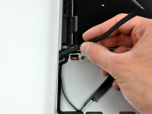
Disconnect the camera cable by pulling the male end straight away from its socket.
-
-
-
Этот шаг не переведен. Помогите перевести
-
Use a spudger to pry the optical drive connector straight up off the logic board.
-
-
Этот шаг не переведен. Помогите перевести
-
Remove the two Phillips screws securing the subwoofer to the upper case.
-
-
Этот шаг не переведен. Помогите перевести
-
Lift the subwoofer off the optical drive, and set it above the computer.
-
-
Этот шаг не переведен. Помогите перевести
-
Remove the two Phillips screws securing the camera cable bracket to the upper case.
-
-
Этот шаг не переведен. Помогите перевести
-
Remove the three 2.5 mm Phillips screws securing the optical drive to the upper case.
-
-
Этот шаг не переведен. Помогите перевести
-
Lift the optical drive from its right edge and pull it out of the computer.
-
-
Этот шаг не переведен. Помогите перевести
-
Remove the single Phillips screw securing the hard drive bracket to the upper case.
-
-
Этот шаг не переведен. Помогите перевести
-
Lift the hard drive by its plastic pull tab and remove the freed hard drive bracket.
-
-
Этот шаг не переведен. Помогите перевести
-
Lift the hard drive out of its supports and disconnect the SATA cable by pulling the connector straight away from the hard drive.
-
-
Этот шаг не переведен. Помогите перевести
-
Remove the four 10.3 mm Phillips screws securing the mid wall to the upper case.
-
-
Этот шаг не переведен. Помогите перевести
-
Use a spudger to pry the hard drive cable connector straight up off the logic board.
-
-
Этот шаг не переведен. Помогите перевести
-
Peel the hard drive cable from the adhesive securing it to the upper case, and maneuver the plastic retaining block out of the upper case.
-


Отменить: Я не выполнил это руководство.
19 участников успешно повторили данное руководство.

3 Комментариев
My mid-2012 MBP MD101LL/A a1278 doesn’t look anything like this, nor does the cable.
These instructions are not for the Mid 2012 A1278, but for a much older MacBook Pro. Pretty confusing.