Введение
Replacing the microphone in your laptop requires the removal of the logic board.
Выберете то, что вам нужно
-
-
With the case closed, place the Unibody top-side down on a flat surface.
-
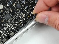
Depress the grooved side of the access door release latch enough to grab the free end. Lift the release latch until it is vertical.
-
-
-
The access door should now be raised enough to lift it up and out of the Unibody.
-
-
-
Grab the white plastic tab and pull the battery up and out of the Unibody.
-
-
-
Remove the following eight screws securing the lower case to the chassis:
-
One 3 mm Phillips screw.
-
Three 13.5 mm Phillips screws.
-
Four 3.5 mm Phillips screws.
-
-
-
Remove the four 10.3 mm Phillips screws securing the mid wall to the upper case.
-
-
-
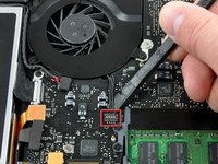
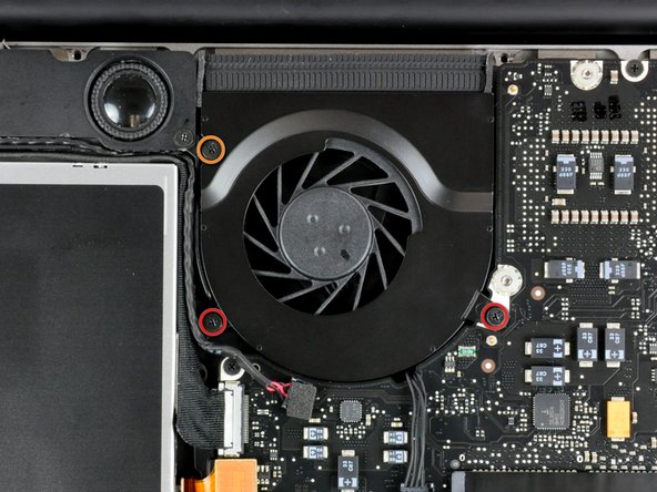
Remove the following three screws securing the fan to the upper case:
-
Two 5 mm Phillips screws.
-
One 7 mm Phillips screw.
-
-
-
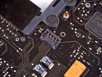
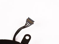
-
Each connector is different, so the following steps will show you how disconnect each in detail.
-
-
-
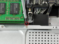
Remove the single Phillips screw securing the battery cable cover to the upper case.
-
Remove the battery cable cover from the upper case.
-
-
-
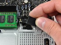
Use a spudger to pry the battery level indicator cable connector straight up off the logic board.
-
-
Инструмент, используемый на этом этапе:Tweezers$4.99
-
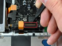
Disconnect the battery cable connector by pulling it straight away from the logic board.
-
-
-
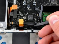
Using the tip of a spudger, flip up the keyboard ribbon cable retaining flap.
-
Pull the keyboard ribbon cable straight out of its socket.
-
If the smaller connector at the right side of the keyboard ribbon cable is populated by another small black ribbon cable, remove it in a similar way to the above.
-
-
-
Use the flat end of a spudger to pry the trackpad connector straight up off the logic board.
-
-
-
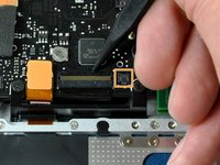
Use the tip of a spudger to flip up the locking lever to release the IR sensor ribbon cable from its socket.
-
Use the tip of a spudger to pull the IR sensor ribbon cable straight away from the logic board.
-
-
-
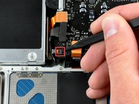
Use the flat end of a spudger to pry the hard drive cable connector straight up off the logic board.
-
-
-
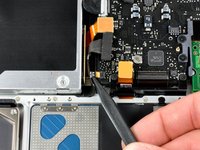
Use the flat end of a spudger to pry the optical drive cable connector straight up off the logic board.
-
-
-
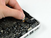
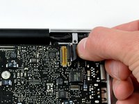
Disconnect the display data cable by pulling the male end straight away from its socket.
-
-
-
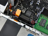
Use the flat end of a spudger to pry the subwoofer cable connector straight up off the logic board.
-
-
-
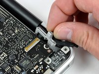
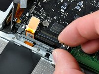
Grab the plastic pull tab secured to the display data cable lock and rotate it toward the DC-in side of the computer.
-
Pull the display data cable connector straight away from its socket.
-
-
-
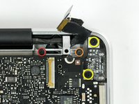
Remove the following two screws securing the display data cable bracket to the upper case:
-
One 7mm Phillips screw.
-
One 5mm Phillips screw.
-
Remove the two 7 mm Phillips screws from the DC-in board.
-
Lift the display data cable bracket out of the upper case.
-
-
-
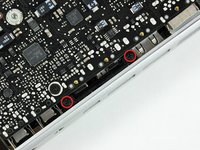
If present, remove the two 4mm Phillips screws securing the bottom case clip to the upper case.
-
Lift the bottom case clip out of the upper case.
-
-
-
Remove the two 5mm Phillips screws securing the keyboard flex bracket to the upper case.
-
Lift the keyboard flex bracket out of the upper case.
-
-
-
Remove the following five screws securing the logic board to the upper case:
-
Four 3mm Phillips screws.
-
One 3.5mm Phillips screw.
-
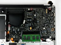
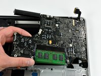
Lift the logic board from its left edge and pull it out of the upper case.
-
-
-
Use the flat end of a spudger to pry the microphone cable connector up off the logic board.
-


To reassemble your device, follow these instructions in reverse order.
To reassemble your device, follow these instructions in reverse order.
Отменить: Я не выполнил это руководство.
3 человек успешно провели ремонт по этому руководству.
