Эта версия возможно содержит некорректные исправления. Переключить на последнюю проверенную версию.
Выберете то, что вам нужно
-
Этот шаг не переведен. Помогите перевести
-
Use tweezers to completely remove the sticker from the rear of controller.
-
-
Этот шаг не переведен. Помогите перевести
-
Find the seven 8.3 mm Phillips screws on the rear of the controller and remove them.
-
-
Этот шаг не переведен. Помогите перевести
-
Use a plastic opening tool to separate the rear and front casing by inserting it in-between the two cases.
-
Use the plastic opening tool to pry the two cases apart.
-
-
-
Этот шаг не переведен. Помогите перевести
-
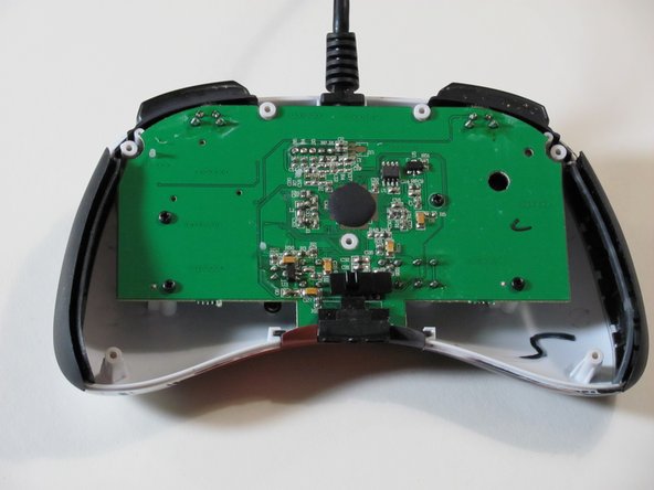
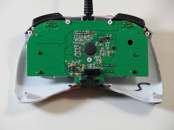
Locate RS-DP-LS switch.
-
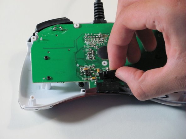
Pull upwards on the switch to remove it.
-
-
Этот шаг не переведен. Помогите перевести
-
Locate the four 8.3 mm Phillips screws on the circuit board and remove them.
-
-
Этот шаг не переведен. Помогите перевести
-
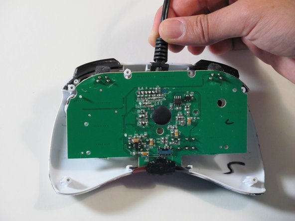
Hold the controller cable at the area just before it meets the controller and slowly lift upwards to slide it out of its plastic slot and remove the circuit board.
-
-
Этот шаг не переведен. Помогите перевести
-
Use tweezers to remove the rubber part of the directional pad.
-
-
Этот шаг не переведен. Помогите перевести
-
Insert a new directional pad over the original directional pad's location.
-


Отменить: Я не выполнил это руководство.
2 участников успешно повторили данное руководство.
Команда

Cal Poly, Team 1-7, Propen Fall 2012 Участник Cal Poly, Team 1-7, Propen Fall 2012
CPSU-PROPEN-F12S1G7
4 членов
Автор 14 руководств
2 Комментариев
mi spiegate l'utilita di questa guida?vendere forse le pinzette e tutte le altre stronzatine che servono per riparare il fightpad?quando invece il pezzo più importante cioè il gommino non lo vendete....fate pena
Hi I don't speak Italian but I think you are asking "what is the purpose of this guide?". We made these as a project for university because I wanted to resolder a wire in this controller that came undone. For good measure we made a guide for each individual part although the real purpose of these guides was for the full disassembly and re soldering.