Перейти к основному содержанию

Эта версия возможно содержит некорректные исправления. Переключить на последнюю проверенную версию.

Абсолютно необходимое руководство
Это руководство предназначено только для использования в качестве обязательного условия для других руководств. Оно не полностью само по себе.

Выберете то, что вам нужно

  1. Этот шаг не переведен. Помогите перевести

    : шаг 1, изображение 1 из 1
    • Remove the five 3 mm T3 Torx screws from the headphone jack/speaker assembly.

  2. Этот шаг не переведен. Помогите перевести

    : шаг 2, изображение 1 из 3 : шаг 2, изображение 2 из 3 : шаг 2, изображение 3 из 3
    • Insert a spudger under the panhandle of the headphone jack/speaker assembly and pry it up from its recess.

    • Remove the headphone jack/speaker assembly.

  3. Этот шаг не переведен. Помогите перевести

    : шаг 3, изображение 1 из 2 : шаг 3, изображение 2 из 2
    • Push the tip of a spudger under the microphone assembly clip to free it from the earpiece speaker.

    • If the assembly clip seems to be missing, check the speaker assembly that was removed from the previous step.

  4. Этот шаг не переведен. Помогите перевести

    : шаг 4, изображение 1 из 2 : шаг 4, изображение 2 из 2
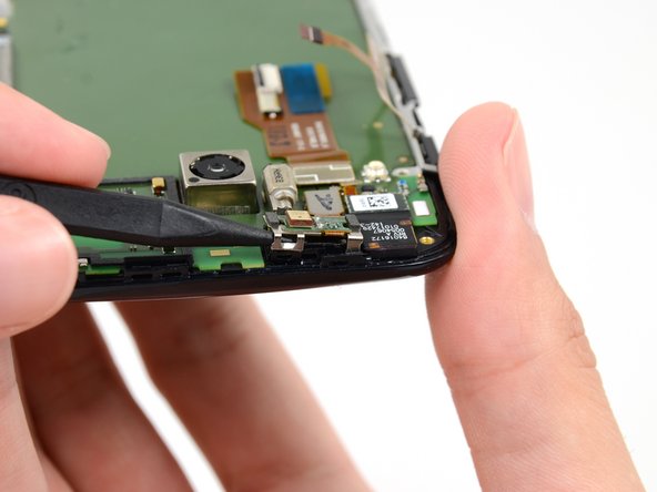
    • Use the flat end of a spudger to free the microphone assembly cable connector.

    • Use tweezers to remove the microphone assembly.

  5. Этот шаг не переведен. Помогите перевести

    : шаг 5, изображение 1 из 2 : шаг 5, изображение 2 из 2
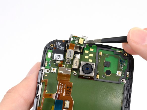
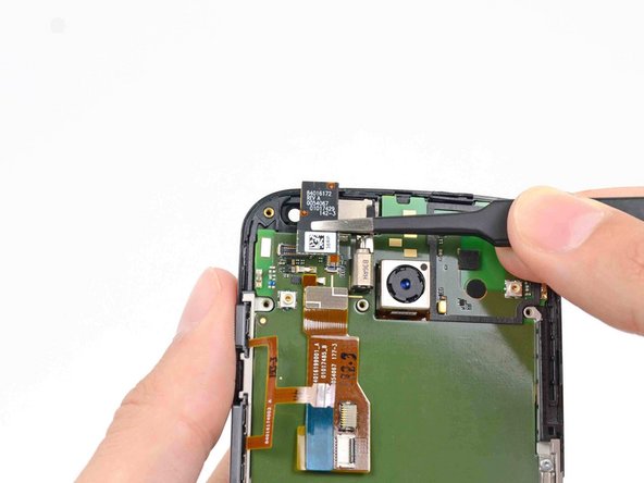
    • Disconnect the front-facing camera cable connector.

    • Remove the front-facing camera from its recess with a pair of tweezers.

  6. Этот шаг не переведен. Помогите перевести

    : шаг 6, изображение 1 из 1
    • Remove the final two 3 mm T3 Torx screws from the SIM slot bracket.

  7. Этот шаг не переведен. Помогите перевести

    : шаг 7, изображение 1 из 1
    • Remove the SIM slot bracket from the motherboard.

  8. Этот шаг не переведен. Помогите перевести

    : шаг 8, изображение 1 из 2 : шаг 8, изображение 2 из 2
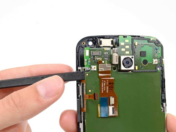
    • Insert the flat end of a spudger under the motherboard above the button assembly cable, and pry it out of the phone.

    • Be careful not to snag any cables.

    • The buttons may pop out of their recesses; take care not to lose them.

  9. Этот шаг не переведен. Помогите перевести

    : шаг 9, изображение 1 из 2 : шаг 9, изображение 2 из 2
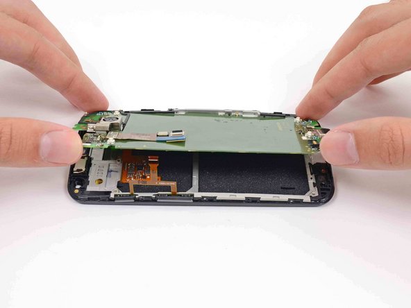
    • Gently lift the motherboard out of the phone, rotating it from the SIM slot edge of the phone.

    • Do not attempt to separate the motherboard entirely; it is still connected to the display by the display cable.

  10. Этот шаг не переведен. Помогите перевести

    : шаг 10, изображение 1 из 3 : шаг 10, изображение 2 из 3 : шаг 10, изображение 3 из 3
    • Lay the motherboard down to allow access to the display cable connector.

    • Use the flat end of a spudger to flip the retaining tab on the display cable ZIF connector.

    • Carefully pull the display cable out of its connector as you remove the motherboard from the display assembly.

Финишная черта

Sam Goldheart

Участник с: 10/18/12

465 869 Репутация

Автор 538 руководств

Команда

iFixit Участник iFixit

Staff

135 членов

Автор 17 214 руководств

0 Комментариев

Добавить комментарий

Просмотр статистики:

За последние 24часов: 0

За последние 7 дней: 7

За последние 30 дней: 10

За всё время: 101