Эта версия возможно содержит некорректные исправления. Переключить на последнюю проверенную версию.
Выберете то, что вам нужно
-
Этот шаг не переведен. Помогите перевести
-
Using a plastic opening tool, remove the thin plastic cover from back of the tablet by prying up from its small tab.
-
-
Этот шаг не переведен. Помогите перевести
-
Remove the five 2mm screws on the back of the device using a PH00 screwdriver.
-
-
Этот шаг не переведен. Помогите перевести
-
Pry the device apart by inserting a plastic opening tool in the seam between the plastic backing and display assembly. Use the tool to unclip the plastic tabs in between the backing and the display.
-
Pull the the plastic backing off the display assembly using your hands.
-
-
Этот шаг не переведен. Помогите перевести
-
Detach the three connector ribbons passing over the battery using the plastic opening tool.
-
-
Этот шаг не переведен. Помогите перевести
-
Remove the twelve 2mm screws around the perimeter of the battery with a PH00 screwdriver.
-
-
Этот шаг не переведен. Помогите перевести
-
Disconnect the battery by lifting it upward and pulling it away from the connector.
-
-
Этот шаг не переведен. Помогите перевести
-
Remove one screw on the logic board with a PH00 screwdriver.
-
-
-
Этот шаг не переведен. Помогите перевести
-
Disconnect right speaker connector ribbon from logic board.
-
Lift the speaker out by pulling up on its corner.
-
-
Этот шаг не переведен. Помогите перевести
-
Disconnect connectors around the perimeter of the motherboard.
-
-
Этот шаг не переведен. Помогите перевести
-
Remove motherboard by gently pulling upward under its corner.
-
-
Этот шаг не переведен. Помогите перевести
-
Remove the three 2mm screws along the right side of the device using a PH00 screwdriver.
-
-
Этот шаг не переведен. Помогите перевести
-
Unseat the small vibrator motor by gently applying upward pressure with a spudger.
-
-
Этот шаг не переведен. Помогите перевести
-
Lift the assembly by gently applying upward pressure with the spudger on the assembly.
-
-
Этот шаг не переведен. Помогите перевести
-
Gently pull battery-audio jack-USB assembly upward, detaching it from its adhesive.
-
-
Этот шаг не переведен. Помогите перевести
-
Detach LCD connector ribbon by pressing upward on connector latch using a plastic opening tool.
-
-
Этот шаг не переведен. Помогите перевести
-
Unscrew the two 2mm Phillips #00 screws holding the ribbon in place.
-
Remove the board by tilting it forward and pulling outward.
-
-
Этот шаг не переведен. Помогите перевести
-
Remove second speaker by gently tilting and pulling upward.
-
-
Этот шаг не переведен. Помогите перевести
-
Unscrew the two 2mm screws securing the micro HDMI connector with a #PH00 screwdriver.
-
Remove the connector by liberally applying upward pressure.
-
-
Этот шаг не переведен. Помогите перевести
-
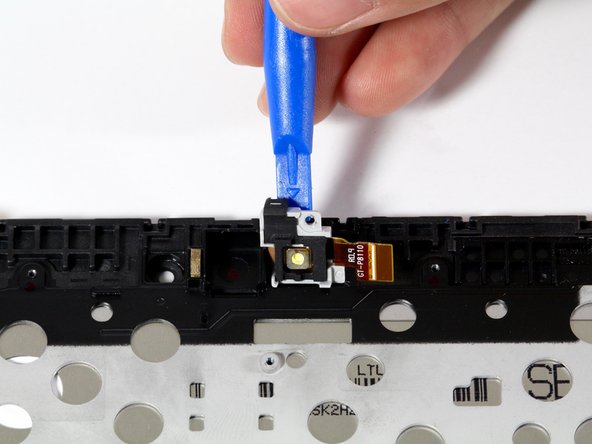
Unscrew the 2mm Phillips #00 screw that holds the flash enclosure.
-
Remove the flash assembly with a plastic opening tool by lifting the assembly upward.
-


Отменить: Я не выполнил это руководство.
6 участников успешно повторили данное руководство.
Команда

Cal Poly, Team 34-18, Maness Spring 2016 Участник Cal Poly, Team 34-18, Maness Spring 2016
CPSU-MANESS-S16S34G18
4 членов
Автор 5 руководств
3 Комментариев
I’m waiting for the instructions regarding how to remove the old screen and insert the new - it seems to be missing
It seems you just have to buy a replacement for that whole front housing, including the screen assembly