Эта версия возможно содержит некорректные исправления. Переключить на последнюю проверенную версию.
Выберете то, что вам нужно
-
Этот шаг не переведен. Помогите перевести
-
Unlatch the battery cover and slide the cover out. Place cover to the side, it will not be needed for the next few steps.
-
Remove the battery.
-
Remove the battery cover without using excessive force. Keep in mind this cover is fragile.
-
-
Этот шаг не переведен. Помогите перевести
-
Remove the two 4.5 mm screws that sit next to the battery slot.
-
Remove the 3 mm screw that sits below the CF card slot.
-
Remove the 4.5 mm screw that sits above the digital I/O cover.
-
-
Этот шаг не переведен. Помогите перевести
-
Remove the two 4.5 mm screws that sit inside the battery slot.
-
-
Этот шаг не переведен. Помогите перевести
-
Remove the two 5 mm screws that sit near the camera strap eyelet.
-
Remove the camera strap eyelet.
-
-
Этот шаг не переведен. Помогите перевести
-
Remove the 5 mm screw and cap that were underneath the camera strap eyelet.
-
-
-
Этот шаг не переведен. Помогите перевести
-
Remove the five 3.5 mm screws that sit at the bottom of the camera.
-
Remove the grey plastic piece, which the five screws held in place, by gently detaching the front cover.
-
-
Этот шаг не переведен. Помогите перевести
-
Using a spudger, detach the white-capped wire.
-
Using a spudger, detach the orange-capped wire and set the front cover aside.
-
-
Этот шаг не переведен. Помогите перевести
-
Detach the grey-capped wire found near the edge of the board.
-
Located next to the blue wires is a green chip. Detach that green chip.
-
-
Этот шаг не переведен. Помогите перевести
-
Remove the 3.5 mm screw that sits next to the rotating lens.
-
You will find that the motherboard is mobile. Flip, or invert the motherboard. Be cautious of the orange and blue ribbon cables. They should still connect the board to the LCD screen.
-
-
Этот шаг не переведен. Помогите перевести
-
Detach the blue ribbon cable.
-
Using a spudger, detach the orange ribbon cable by pushing it out horizontally.
-
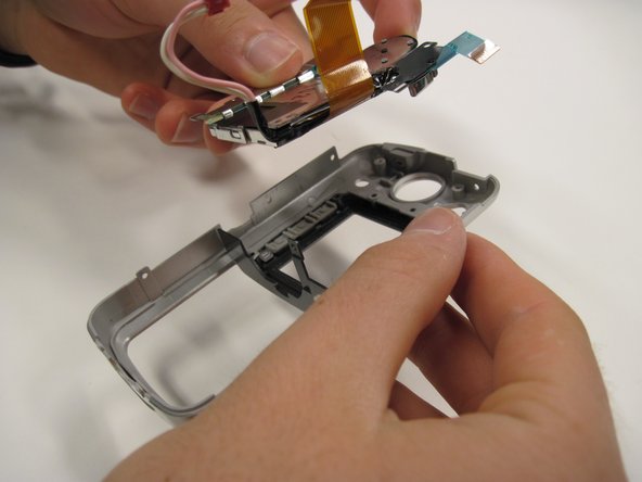
Detach the red-capped wire.
-
Lift the logic board and lens out of the back cover. Be sure that they are connected.
-
-
Этот шаг не переведен. Помогите перевести
-
Lift the black covering
-
Remove the orange ribbon cable that connects the lens to the logic board.
-
-
Этот шаг не переведен. Помогите перевести
-
Remove the 2.5 mm screw.
-
Remove the two 3.4 mm screws.
-
Remove the two 4.4 mm screws.
-


Команда

Cal Poly, Team 30-38, Garner Spring 2010 Участник Cal Poly, Team 30-38, Garner Spring 2010
CPSU-GARNER-S10S30G38
5 членов
Автор 11 руководств