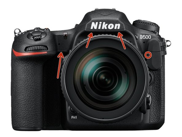
Введение
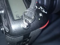
I had a failure of the Metering Mode Button, and after several times reseating the connector, it just totally failed and the fix no longer worked.
I acquired a replacement top assembly from AliExpress.
Выберете то, что вам нужно
-
-
Remove the Memory Card(s) from the camera
-
Remove the Battery from the Camera, and close the battery compartment cover
-
-
-
Remove the 2 screws beside the memory slots, then close the cover.
-
Note: make sure to remove the memory cards first!
-
-
-
Remove the 2 screws under the rubber grip part by peeling back the rubber grip
-
Try not to damage the double sided adhesive under the rubber.
-
-
-
Remove the 2 screws under the rubber pad marked in red.
-
Try not to damage the double-sided adhesive under the rubber.
-
Note: There is a 3rd screw under the flap, which holds the back to the top (marked in yellow). If needing to remove the back panel not just the memory cover flap, it can be removed at this time as well.
-
-
-
Lift out the assembly panel, it should come free without much force.
-
May open the panel to release it.
-
-
-
Remove the 4 screws holding the plate to the bottom.
-
Remove the bottom plate
-
-
-
Remove the 4 screws (1 was under the plate removed under the last step)
-
-
-
-
Remove the screw under the grip, if it has not been removed doing a previous step
-
-
-
Carefully pull the back plate off the camera
-
There are 2 ribbon cables that need to be disconnected from the main board to free the rear panel from the camera.
-
To release the cables by flipping up the tap on the side away from the cable
-
When reconnecting the cables, make sure the cables are fully seated before flipping the latch back down.
-
The black cable goes to the LCD (on the tilt screen), the other one goes to the buttons.
-
The black LCD cable does have less slack, so is easier to release first, and reconnect last.
-
-
-
Carefully remove the Rubber grip from the camera
-
Careful to not damage the double-sided adhesive
-
-
-
Carefully remove the Rubber grip from the camera
-
Careful to not damage the double-sided adhesive
-
-
-
Remove the diopter cap from the end of the diopter (use a flat head or pry tool)
-
Un-screw the phillips screw from the diopter
-
When reconnecting, make sure the cap is seated in correctly and the double sided tape is not damaged (or replace)
-
There is a notch which the indicator has to seat into, or it will not sit down correctly when it is reinstalled.
-
-
-
Remove the screw that had been hidden under the memory slot cover.
-
-
-
Remove the screw under the top assembly, had been hidden by the grip.
-
Remove the 2 screws from the bottom of the mirror box
-
Remove the lens or lenscap prior to doing this step to gain access, then reattach.
-
Remove the screw from beside the accessory socket
-
-
-
Remove the screw from the left side, had been hidden under the rubber
-
-
-
Disconnect the 2 ribbon cables from the main board (Red boxes)
-
Lift the black tabs above the cables to release the cables
-
When reseating the cables, make sure they are fully seated before closing the locking tab
-
Note: there is another ribbon cable under the left one which goes to the 10-pin accessory port, make sure it's seated correctly when reassembling.
-
Disconnect the wifi sub-board with the wifi cable from the main board (Blue Box) or gently disconnect the wifi antenna (Blue circle)
-
The antenna connector is very delicate, and isn't designed for many cycles, which is why the board is recommended (it has a socket it fits into.
-
-
-
Carefully lift the top assembly free.
-
Note, there is a thermal pad on the left hand side, almost right under where the strap lug is. Red Box. Careful to not damage it.
-
-
-
Reassemble the camera using the replacement part, with the steps in the reverse order
-
Make sure all ribbon cables are fully seated before closing the latch, or the camera may not work correctly
-
Many screws are into plastic, make sure to not over-tighten them
-
Make sure the camera is fully functional, to confirm all the parts were connected correctly.
-
-
-
(This step can be done before removing the top assembly from the camera, if desired)
-
Remove the existing strap from the camera
-
Remove the black plastic retainer clips by pushing them towards the camera
-
Using a metal pry tool, open the split ring and rotate it through the mount point to release it from the camera
-
Repeat the steps for the other side.
-
-
-
(This step can be done before removing the existing top assembly, but is easier after installing it)
-
Using the metal spudger to hold the split ring open slide it into the mount on the new top assembly.
-
Keeping the side which has the 2 ends of the split ring either to the front or back, and the flat side away from the camera one of the other side, slide the black retainer clip onto the split ring, with the solid side away from the camera while the clip is the way a strap would hold it.
-
Repeat the step for the other side.
-
Reattach the neck strap to the connectors
-


Test to make sure all the parts are working. If any are not, it could be just a ribbon cable did not get seated correctly.
Test to make sure all the parts are working. If any are not, it could be just a ribbon cable did not get seated correctly.
