Эта версия возможно содержит некорректные исправления. Переключить на последнюю проверенную версию.
Выберете то, что вам нужно
-
Этот шаг не переведен. Помогите перевести
-
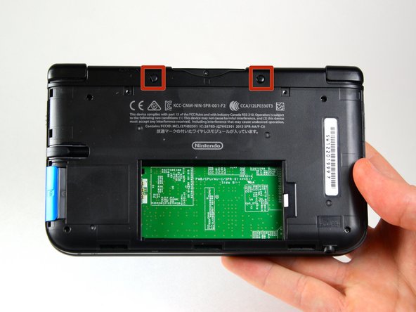
Loosen the two #0 Phillips 4.2 mm-length screws located at the top of the back cover.
-
-
Этот шаг не переведен. Помогите перевести
-
Hold the device so that the cover is facing up.
-
Using a plastic opening tool, pry off the cover starting at the top right corner.
-
Hold the edge of the cover to ensure it does not reattach.
-
Look for the small section below the stylus compartment. Pry off the cover at that point if it is still attached.
-
Take off the cover of the device and set it aside.
-
-
Этот шаг не переведен. Помогите перевести
-
Insert the plastic opening tool into the opening located on the right side of the battery.
-
Pry off the battery from the lower casing.
-
Lift the battery out of the case and set aside.
-
-
Этот шаг не переведен. Помогите перевести
-
Using tweezers pull out the rubber bumpers that are located at the top of the device on either side of the game cartridge compartment.
-
-
Этот шаг не переведен. Помогите перевести
-
Remove the six 6.2 mm screws using a Phillips #00 screwdriver
-
-
Этот шаг не переведен. Помогите перевести
-
Remove the 2.3 mm screw located above the game cartridge slot with a Phillips #00 screwdriver.
-
-
Этот шаг не переведен. Помогите перевести
-
Make sure the SD card has been removed. With a plastic opening tool pry off the lower case starting at the bottom edge and working around the perimeter.
-
Two ribbon cables connect the case to the circuit board. Be careful to not pull the case too hard and rip the ribbon cables.
-
-
Этот шаг не переведен. Помогите перевести
-
Remove the ribbon cables located underneath the left and right bumpers by prying up the base of the cables with a plastic opening tool.
-
Completely remove the lower case from the rest of the device and set aside.
-
-
-
Этот шаг не переведен. Помогите перевести
-
Position the device such that the game cartridge slot is located at the top.
-
Locate the circle pad on the right side of the device.
-
Remove the two 7.5 mm screws on the upper left and the bottom right corners.
-
-
Этот шаг не переведен. Помогите перевести
-
Using a plastic opening tool pop off the circle pad joystick.
-
Do not use excessive force with the plastic opening tool. There is a ribbon attaching the circle pad joystick to the motherboard that will remain attached.
-
-
Этот шаг не переведен. Помогите перевести
-
Using the flat head side of the spudger carefully lift up the retaining flap that attaches the circle pad ribbon to the motherboard.
-
Remove the ribbon and circle pad joystick.
-
-
Этот шаг не переведен. Помогите перевести
-
Position the device such that the game cartridge slot is located at the top.
-
Locate the IR board located on the upper right side of the motherboard.
-
Remove the IR board with a plastic opening tool by inserting the tool below the IR board and gently prying up.
-
-
Этот шаг не переведен. Помогите перевести
-
Using a plastic opening tool, pry off the Wi-Fi board.
-
The Wi-Fi board will still be connected by a wire and it is not necessary to completely remove it for this step. Simply place it out of the way for this step.
-
-
Этот шаг не переведен. Помогите перевести
-
Locate the volume switch on the right side of the motherboard next to the circle pad joystick.
-
Using tweezers, carefully remove the volume board from the casing. It will still be attached to the motherboard by a ribbon cable.
-
-
Этот шаг не переведен. Помогите перевести
-
Using the flat head side of the spudger carefully lift up the flap that attaches the volume board ribbon to the motherboard.
-
Remove the volume board and set aside.
-
-
Этот шаг не переведен. Помогите перевести
-
Remove the black plastic pieces from the lower left and right hand corners with either your fingers or tweezers.
-
You can also remove these pieces easily by carefully lifting up the 3DS and holding it upside-down. They normally fall right out, but don't lose them!
-
-
Этот шаг не переведен. Помогите перевести
-
Using the flat head side of the spudger carefully lift up the flap that attaches the two smaller ribbons to the motherboard.
-
These flaps are located on the top right and bottom right side of the motherboard.
-
Remove the ribbons from the flap.
-
-
Этот шаг не переведен. Помогите перевести
-
Using the flat head side of the spudger carefully lift up the flaps that attach the wider ribbons to the motherboard.
-
Remove the ribbons from the opened flaps.
-
-
Этот шаг не переведен. Помогите перевести
-
Using the flat head side of the spudger carefully lift up the flap that attaches the ribbon to the motherboard.
-
Remove the ribbon from the flap.
-
-
Этот шаг не переведен. Помогите перевести
-
Remove ten 3.0 mm screws that are located around the face of the motherboard.
-
-
Этот шаг не переведен. Помогите перевести
-
Carefully lift the board straight up just enough to clear the two plastic mounts located near the top corners of the cartridge slot.
-
Gently flip the motherboard over the top side.
-
-
Этот шаг не переведен. Помогите перевести
-
Using the flat head side of the spudger carefully lift up the flap that attaches the wider ribbon on the upper right side to the motherboard.
-
Remove the ribbon from the opened flap.
-
Set the motherboard aside.
-
-
Этот шаг не переведен. Помогите перевести
-
Open the device's hinge.
-
Gently press upward on the touchscreen until it separates from the casing.
-


Отменить: Я не выполнил это руководство.
62 участников успешно повторили данное руководство.
Команда

Cal Poly, Team 9-13, Regan Spring 2014 Участник Cal Poly, Team 9-13, Regan Spring 2014
CPSU-REGAN-S14S9G13
5 членов
Автор 44 руководств
24 Комментариев
what if you need to replace the screen on the top housing? what is it called.
Is the bottom LCD screen of the Nintendo 3ds xl, the same as the one in the NEW Nintendo 3ds xl?
Looking for what part to buy.
Bit old, but did you figure out the answer which to buy?
White -
Very detailed and easy to use step by step thanks. However, after reassembly after I switch the power button on it starts and then a flash and it trips out? Obviously a fault somewhere but not sure where to start.? Any thoughts appreciated.
That's to do with a part this tutorial skips: you need to put some insulation between the new screen and the motherboard. That's what that orange film is on the back of the screen in the photos. When replacing, you can easily (carefully) remove that film and stick it onto the back of the new screen, no problem. Or you can put some other sort of adhesive to create some insulation between the screen and motherboard. Hope this helps.