Перейти к основному содержанию

Эта версия возможно содержит некорректные исправления. Переключить на последнюю проверенную версию.

Абсолютно необходимое руководство
Это руководство предназначено только для использования в качестве обязательного условия для других руководств. Оно не полностью само по себе.

Выберете то, что вам нужно

  1. Этот шаг не переведен. Помогите перевести

    : шаг 1, изображение 1 из 3 : шаг 1, изображение 2 из 3 : шаг 1, изображение 3 из 3
    • Close the DSi XL and turn it over.

    • Using a pair of tweezers, pull the microphone out of its housing in the front bezel.

    • De-route the microphone cable, and pull it through the right hinge.

  2. Этот шаг не переведен. Помогите перевести

    : шаг 2, изображение 1 из 3 : шаг 2, изображение 2 из 3 : шаг 2, изображение 3 из 3
    • Using the flat end of a spudger, pry the left speaker out of its socket on the front bezel.

    • De-route the speaker cable along the top edge of the screen.

    • Work carefully and slowly, holding onto the wire and not the speaker itself. The solder joints may break if pulled on too hard.

    • In the same manner described above, remove the right speaker from its socket on the front bezel.

    • Place both speakers on the back of the upper LCD.

  3. Этот шаг не переведен. Помогите перевести

    : шаг 3, изображение 1 из 2 : шаг 3, изображение 2 из 2
    • Ensuring that the upper LCD does not fall out of the front bezel, turn the DSi XL over.

    • Remove the seven 2.5 mm silver screws securing the power board to the upper case.

    • Lift the power board up off the upper case.

  4. Этот шаг не переведен. Помогите перевести

    : шаг 4, изображение 1 из 2 : шаг 4, изображение 2 из 2
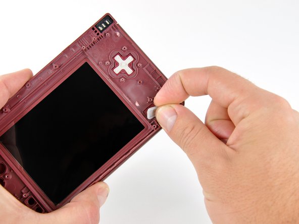
    • Peel the rubber button pads off the backside of the D-pad and power button.

  5. Этот шаг не переведен. Помогите перевести

    : шаг 5, изображение 1 из 2 : шаг 5, изображение 2 из 2
    • Open the case slightly.

    • Push the D-pad up through its housing in the upper case. Remove the D-pad.

    • In the same way, remove the power button from the upper case.

  6. Этот шаг не переведен. Помогите перевести

    : шаг 6, изображение 1 из 2 : шаг 6, изображение 2 из 2
    • Using a pair of tweezers, remove the LED diffuser bracket and the LED diffuser from the upper case of the DSi XL.

  7. Этот шаг не переведен. Помогите перевести

    : шаг 7, изображение 1 из 3 : шаг 7, изображение 2 из 3 : шаг 7, изображение 3 из 3
    • In the following steps, you will be using a spudger to remove the hinge pin from the left side of the DSi XL.

    • Place the tip of a spudger in the LED diffuser compartment, on the face of the clutch hinge.

    • Push the clutch hinge to the left.

    • Some force will be required. You will hear an audible "pop" when the clutch has cleared the lower case. It will move about 0.25".

  8. Этот шаг не переведен. Помогите перевести

    : шаг 8, изображение 1 из 2 : шаг 8, изображение 2 из 2
    • Lift the left side of the front bezel away from the upper case.

    • Do not lift too far, or else the hinge pin will break. Only lift enough to clear the LED compartment, about 1".

    • Pull the front bezel to the left, separating the front bezel from the upper case.

    • Do not attempt to fully separate the two halves yet. There are still ribbon cables running through the upper case.

  9. Этот шаг не переведен. Помогите перевести

    : шаг 9, изображение 1 из 3 : шаг 9, изображение 2 из 3 : шаг 9, изображение 3 из 3
    • Grasp the camera and upper LCD ribbon cables between your thumb and forefinger, pulling them out of the upper case slightly, slide them down through the slit in the upper case.

    • Rotate the front bezel assembly clockwise so that the ends of the camera and LCD cables slide sideways through the slit in the front bezel.

  10. Этот шаг не переведен. Помогите перевести

    : шаг 10, изображение 1 из 2 : шаг 10, изображение 2 из 2
    • In order to remove the upper LCD and the cameras from the front bezel, it is helpful to coil the ribbon cables together.

    • Carefully coil the two ribbon cables together, so that the connectors are on the inside of the spool.

    • Wrap the ribbon cables tightly, but not too tight, as bending the connectors will render them inoperable.

  11. Этот шаг не переведен. Помогите перевести

    : шаг 11, изображение 1 из 2 : шаг 11, изображение 2 из 2
    • Holding the upper LCD and the cameras together, pull the cables through the hinge in the front bezel.

    • Pull slowly, making sure that the cables do not catch on the hinge pin and tear.

    • Uncoil the ribbon cables.

Финишная черта

Brett Hartt

Участник с: 04/12/10

127 920 Репутация

Автор 143 руководств

Команда

iFixit Участник iFixit

Staff

135 членов

Автор 17 188 руководств

0 Комментариев

Добавить комментарий

Просмотр статистики:

За последние 24часов: 0

За последние 7 дней: 9

За последние 30 дней: 9

За всё время: 1,737