Эта версия возможно содержит некорректные исправления. Переключить на последнюю проверенную версию.
Выберете то, что вам нужно
-
Этот шаг не переведен. Помогите перевести
-
Remove the two Phillips screws securing the battery cover to the back of the handheld console.
-
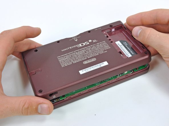
Lift the battery cover off the back of the DSi XL.
-
-
Этот шаг не переведен. Помогите перевести
-
Remove the four rubber screw covers on the lower case by prying them up with a push pin.
-
-
-
Этот шаг не переведен. Помогите перевести
-
Remove the following seven Phillips screws that secure the lower case to the rest of the DSi XL:
-
Four silver 5.3 mm screws
-
Two black 5.3 mm screws
-
One black 2.5 mm screw
-
-
Этот шаг не переведен. Помогите перевести
-
Insert a spudger between the upper and lower case at the bottom left corner of the DSi.
-
Slide the spudger along the bottom edge of the upper case to release the latches securing the upper case to the lower case.
-
-
Этот шаг не переведен. Помогите перевести
-
Lift the lower case from the front edge.
-
Rotate the lower case away from the DSi.
-
-
Этот шаг не переведен. Помогите перевести
-
Using a spudger, pry the SD card/right shoulder button connector off its socket.
-
Pry the volume button/left shoulder button connector off its socket on the motherboard with a spudger.
-
-
Этот шаг не переведен. Помогите перевести
-
Lift the Wi-Fi board up off its socket on the motherboard.
-
-
Этот шаг не переведен. Помогите перевести
-
Use a spudger to pry the Wi-Fi cable off its socket on the underside of the Wi-Fi board.
-


Отменить: Я не выполнил это руководство.
10 участников успешно повторили данное руководство.

