Введение
This guide will show how to effectively disassemble the Game boy advance SP and gain access to the logic board, all the buttons (trigger buttons a common problem), the battery, and the speaker.
Выберете то, что вам нужно
-
-
Using a Phillips 000 driver, loosen the screw securing the battery compartment.
-
Using a metal spudger, gently lift the battery compartment by placing the edge just under the screw. The screw will come off with the cover as it has a washer holding it in place.
-
Remove battery using a plastic spudger or fingernail.
-
-
-
-
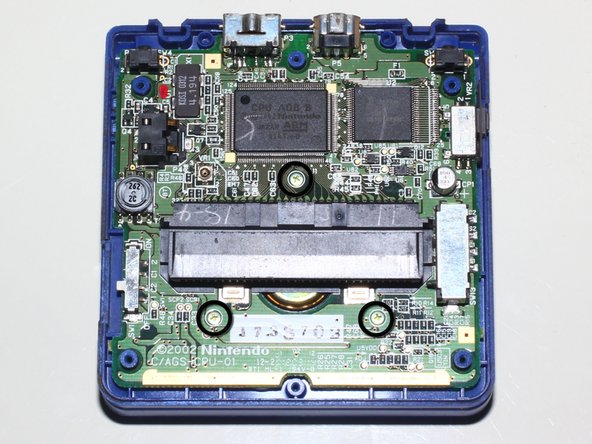
Back cover contains 4 Gold Tri-Wing #0 screws (Red circle), and 2 Silver Tri-Wing #0 Screws (Yellow circle).
-
Remove screws and lift back cover off giving access to motherboard.
-
Motherboard is secured by 3 Phillips #0 screws.
-
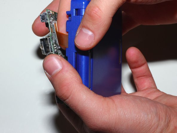
Triggers L&R (Orange box), and Power Switch Piece (Yellow box) are found affixed to the rear cover.
-


To reassemble your device, follow these instructions in reverse order.
To reassemble your device, follow these instructions in reverse order.
Отменить: Я не выполнил это руководство.
10 участников успешно повторили данное руководство.

3 Комментариев
It appears that the tri-wing screw heads are not really Y0 - certain kits that have Y0 bits, like the Harbor Freight Electronics Repair Kit, did not work for me. I wonder if it's 00, or something metric. If you're shopping, beware of interchangeable bits that are too short or shafts that are too fat, as well.
Oh, the "Y1" screwdriver that the page "recommends" (sells) in the display at the bottom of the guide is definitely wrong as well. Since Y0 was too large, Y1 definitely wouldn't fit.
I ended up getting a 5-pack of special-made screwdrivers (all of the same one).
These work fine, even on a couple of screws that I stripped a little while trying the aforementioned Y0.
I suspect it's some standard size, but I have no way to tell for sure. The markings on it are "360/(Y)x50" but the only standard thing I can decipher from that is that the "x50" might refer to the 5 cm shaft length. :/
Cheapest price I found for a single driver is about $2-3, or $6 for the 5-pack I got.
AySz88 -