Этот документ имеет более свежие изменения. Перейти к последней непроверенной версии.
Введение
Follow this guide to replace the motherboard in a Nintendo Switch video game console.
Выберете то, что вам нужно
-
-
Press and hold down the small round button on the back of the Joy Con controller.
-
While you hold down the button, slide the controller upward.
-
-
-
Continue sliding the Joy Con upward until it's completely removed from the console.
-
-
-
Use a Y00 screwdriver to remove the four 6.3 mm-long screws securing the rear panel.
-
-
-
Use a JIS 000 driver or an official iFixit PH 000 driver to remove the following screws securing the rear panel:
-
One 2.5 mm-long screw on the top edge of the device
-
Two 2.5 mm-long screws on the bottom edge of the device
-
-
-
Use a JIS 000 screwdriver or an official iFixit PH 000 driver to remove the two 3.8 mm center screws on the sides of the device (one on each side).
-
-
-
Use a JIS 000 screwdriver or an official iFixit PH 000 driver to remove the 1.6 mm screw in the kickstand well.
-
Close the kickstand.
-
-
-
Open the game card cartridge flap.
-
Lift the rear panel up from the bottom of the device and remove it.
-
-
-
Use a JIS 000 screwdriver or an official iFixit PH 000 driver to remove the six 3 mm screws securing the shield plate to the device.
-
-
-
Use your fingers or a pair of tweezers to peel back the piece of foam on the top edge of the device near the fan exhaust port.
-
-
-
Insert a spudger underneath the shield plate along the edge of the device.
-
Pry up to lift the shield plate and remove it from the device.
-
You can reuse the pink thermal compound if you're careful. Keep the compound clean and make sure it makes solid contact between the heat sink and the shield during reassembly.
-
If you need to replace it, refer to our thermal paste guide to remove the old thermal compound and replace it with an appropriate compound, such as K5 Pro, during reassembly.
-
-
-
Use the point of a spudger to pry the battery connector straight up and out of its socket on the motherboard.
-
-
-
-
Use a JIS 000 screwdriver or an official iFixit PH 000 driver to remove the three 3 mm screws securing the heat sink to the motherboard.
-
-
-
Carefully peel the two foam pieces stuck over both the heatsink and the fan away from the fan.
-
Insert the point of a spudger underneath the part of the foam that isn't stuck against anything,
-
Press the top of the foam with your finger to hold it in place.
-
Roll the spudger tip underneath the foam all the way to the other end of the foam to release it.
-
-
-
Use a spudger or your fingers to lift the heatsink up and off the motherboard to remove it.
-
Apply thermal paste to all surfaces that had thermal paste applied previously. This includes between the heatpipe and aluminum shield, which the Switch uses as additional heatsinking.
-
-
-
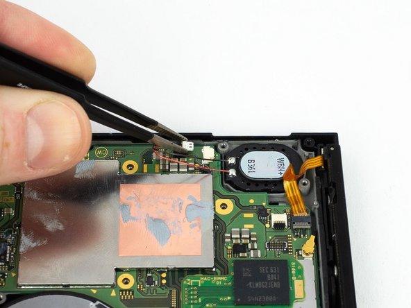
Use an opening tool or your fingernail to flip up the small, hinged locking flap on the digitizer cable's ZIF connector.
-
-
-
Use a pair of tweezers to slide the digitizer cable horizontally out of its connector on the game card reader board.
-
-
-
Use the point of a spudger to pry the headphone jack and game card reader connector straight up to disconnect it from the motherboard.
-
-
-
Use a JIS 000 screwdriver or an official iFixit PH 000 driver to remove the three 3.1 mm screws securing the headphone jack and game card reader board to the device.
-
-
-
Use a pair of tweezers or your fingers to remove the headphone jack and game card reader board.
-
-
-
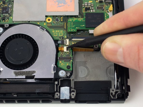
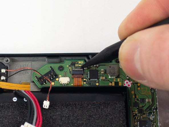
Use a spudger to flip up the small beige locking flap on the display ZIF connector.
-
-
-
Use the pointed end of a spudger to slide the display ribbon cable out of the ZIF connector.
-
-
-
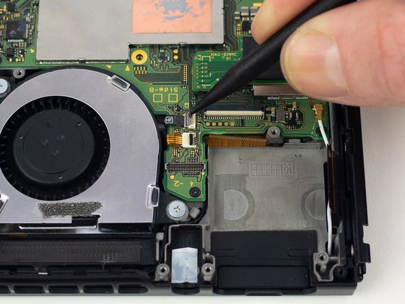
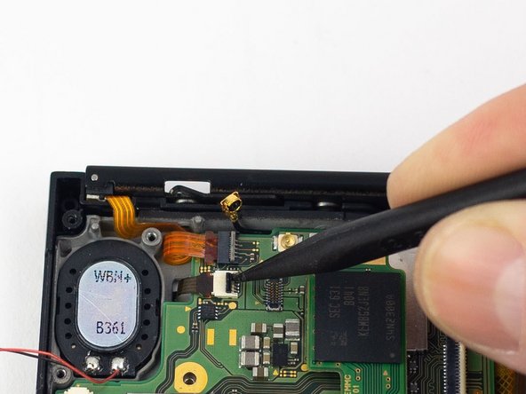
Use a spudger to flip up the small black locking flap on the power/volume button ZIF connector.
-
-
-
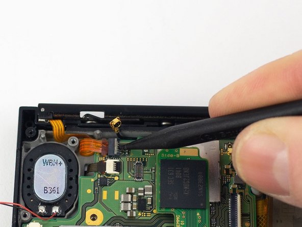
Use the flat end of a spudger to disconnect the white coaxial antenna cable from the motherboard.
-
-
-
Use the flat end of a spudger to disconnect the black coaxial antenna cable from the motherboard.
-
-
-
Use a spudger to flip up the small gray locking flap on the right Joy-Con rail ZIF connector.
-
-
-
Use a spudger to flip up the small gray locking flap on the left Joy-Con rail ZIF connector.
-
-
-
Remove the four 2.50 mm JIS #000 screws from the motherboard.
-
Remove the two 3.14 mm JIS #000 screws from the USB-C port.
-


To reassemble your device, follow these instructions in reverse order.
To reassemble your device, follow these instructions in reverse order.
Отменить: Я не выполнил это руководство.
91 участников успешно повторили данное руководство.

18 Комментариев
You can buy one on the ifixit parts store or you can find a used one on eBay.
What’s the name of the grey compound you insert on the cooper section on the motherboard? I’ve been wondering what that stuff is.
That is thermal compound or commonly known as thermal paste. It improves performance of parts by bridging the gaps between the CPU and heat pipes.